J310 is on slow boat from China - maybe 3 more weeks. It is not available anymore from Digikey. So a 1.5k resistor between the tail of 2SK170 LTP and the 100R pot will allow me to test the circuit sans J310? So if I only have a 500R pot, a 1k should be fine?
No you need 100 ohm, because of current sharing, you get trouble when these are bigger, you can use 1.5 K, maybe a 500 ohm in driver section for idle current is good idea for test, set it on highest resistance and see what happens, 50 a 60 ma total current is when sim,
a work around is two 47 ohm resistors as pot, but you can not adjust, with some luck output offset is not that bad.
Here things do work, the oscilloscoop did let see it works but openloop give terrible output. you can test the preamp by remove the powerfets, and set SV and SV2 to local, connect gate resistors irfp240 to feedback loop, and see what happens, it do then works as a amp.
I have also to wait, some resistors and the PN4391 and J310 are on his way.
The first order 100 pieces of fuse holders are quite quick from Hong Kong, two weeks, maybe it is blow here because of the hurricane.
Last edited:
Ok I keep two 47R resistors and test that way. So pull out J113's and put in 1.5k to complete the circuit. What should I be looking for to confirm that it works? Correct current of 10mA total and circa 12v at gates of ZVN's? What about gates of IRF610/9610? Do the 610/9610's need to be installed to test circuit?
I have not install the irf in the circuit, only the part with zvn and 2sk170 and the resistor, I did see for the 1.5k resistor I have use now a 1,8k because then I did get 23 volts on the two 2.2k R15 and R14 where gates of irf are connected, this will open the irf9610 .
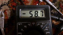
you can test it by measure on the gates fo the irf9610 I did it on the resistors, see if you get 23 volts or around, and look on the other resistor how much it is off, need both same voltage but not matched 2sk170 will give error, and without pot you can not balance it.
when you put audio in, only balanced will work with a resistor.
Because you have a cirlcoltron with 25 volts supply, you need to lower the 5.6K feedback resistors and put bigger caps, like 150pF, later on when working all you can these with a square wave on 20 Khz, and take overshoot out.
I did blow mine one hour ago, by connect wrong, maybe in future a couple skotchy diodes can protect the driver section for destroying, for the output section this is less prone because fuse will blow.
You can put in the irfp610 and 9610 but make the idle pot resistance 500 ohms and set for max to protect and see what happens, so you have more room, and when ready put then the 47 ohm in, You can use later the current source resistor j310 to tune that in so it falls within the 47 ohm, and have a nice responding setting.
Amp is a little more complicated als you have made last, we have circlotron and this need more attention.
Th blowing of mine was only a cap blowing in my face, but no damages on the rest, so is quite immuun. except afcause when irf are in then it blow more easy, I have not set current protection of the supply on 100 ma so this do not happen anymore.
What I have slao done is change the 100 ohms resistors R7 and R25 on 2sk170 sources to 47 ohms, it did respons better on feedback.
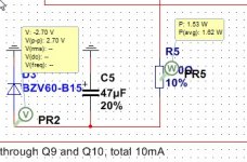
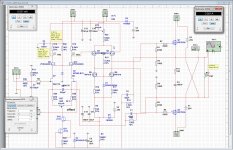
My sim program has strange habbit, I get rare simm effect when put decoupling caps, a zener do slowly to his voltages, but when sim in a new sheet with only zener, cap, resistor (see picture) it was not a problem, get right away that 15 volts while in complete amp it go slowly up getting 1.8 watts on the resistor R4 680 ohm. Strange software.
I have not yet the resistors, so testing with irf is not yet possible. but it looks good, quite god results close to sim.
regards
you can test it by measure on the gates fo the irf9610 I did it on the resistors, see if you get 23 volts or around, and look on the other resistor how much it is off, need both same voltage but not matched 2sk170 will give error, and without pot you can not balance it.
when you put audio in, only balanced will work with a resistor.
Because you have a cirlcoltron with 25 volts supply, you need to lower the 5.6K feedback resistors and put bigger caps, like 150pF, later on when working all you can these with a square wave on 20 Khz, and take overshoot out.
I did blow mine one hour ago, by connect wrong, maybe in future a couple skotchy diodes can protect the driver section for destroying, for the output section this is less prone because fuse will blow.
You can put in the irfp610 and 9610 but make the idle pot resistance 500 ohms and set for max to protect and see what happens, so you have more room, and when ready put then the 47 ohm in, You can use later the current source resistor j310 to tune that in so it falls within the 47 ohm, and have a nice responding setting.
Amp is a little more complicated als you have made last, we have circlotron and this need more attention.
Th blowing of mine was only a cap blowing in my face, but no damages on the rest, so is quite immuun. except afcause when irf are in then it blow more easy, I have not set current protection of the supply on 100 ma so this do not happen anymore.
What I have slao done is change the 100 ohms resistors R7 and R25 on 2sk170 sources to 47 ohms, it did respons better on feedback.
My sim program has strange habbit, I get rare simm effect when put decoupling caps, a zener do slowly to his voltages, but when sim in a new sheet with only zener, cap, resistor (see picture) it was not a problem, get right away that 15 volts while in complete amp it go slowly up getting 1.8 watts on the resistor R4 680 ohm. Strange software.
I have not yet the resistors, so testing with irf is not yet possible. but it looks good, quite god results close to sim.
regards
Attachments
Last edited:
You can order the J310 from Mouser and you can easily use the SOT-23 package if you're confortable soldering SMD components. It is actually quite cheap in SMD. Source and drain are interchangeable.
Do
Do
You can order the J310 from Mouser and you can easily use the SOT-23 package if you're confortable soldering SMD components. It is actually quite cheap in SMD. Source and drain are interchangeable.
Do
Maybe if it works well, we can try a version with smt components, but for power amps it is safer and easyer when using through hole, when blow more easy to repair.
But thanks for the idea
regards
Good progress Kees. Looks like a lot of little changes described there - please update a new schematic and stuffing diagram with revised part values. I will wait until you get it sorted out and for my pots and J310 to arrive before attempting this again. It's a lot of manual fine tuning because it is a brand new straight from your brain amp. 🙂
If it were me, because I am not an mp designer, I would have just lifted a tried and true differential input stage with CCS from another amp and not deal with all this very fine DC balancing act. It is strange that the initial sims showed all the DC components behaving nicely. What is it about the implementation per the original design that threw all this off? The J113 could not supply enough current?
A few questions:
If J310 is the common CCS, why is a pair of ZVN's needed above the JFET LTP? Could not resistors have been used there as well? Or is it that the 2SK170's cannot drive the IRFP610's directly? I know that's not true because I just built a headphone amp where a pair of 2SK170/2SJ74's drive IRFP610/9610 directly for a low impedance audio amp. No intermediate stages.
Also, why is it that if I replace the cascode J310 with a resistor, I have to use balanced inputs? Does grounding the gate on one side of the LTP cause a problem when using a resistor?
I'm sure there are obvious answers as I am not an amp designer.
Thanks.
Hi x
Correction, a resistor did work also with unbalanced setting, however to get things stable we need the current source, it does give a constant current a resistor can not give, also when you use a resistor the hum of the supply get through, maybe that is also a reason to use a current source, I think the PN 4391 who has the highest current is best, J310 can be used also you therefore all diff amps with lower current sources, like mirror, wilson etc but now you can experience with the amp, just build the other pcb again and try, include the irf mosfets and see what happens.
The J113 is to weak in current, the others can do 25 mA to 60 mA and this is more then enough, idss is higher also. Maybe there can be better ones but this will do fine.
The resistor is just a way so you can start experiencing, later you need to correct, because feedback do also not work fine.
So we need for shure the J310 and tune them.
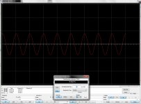
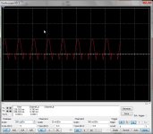
Here output from amp with resistor, nothing can be adjusted because of feedback error.
Yes maybe it is better to wait for me because it is more complicated and quite new idea, however the parts in the amp are already invented but I did use a different combination.
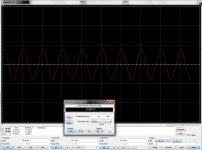
Pictures with unbalanced feed, Q 2 gate grounded, and with a current resistor, it do have higher distortion but not much, I think supply hum will problem when use not a current source.
X just begin, you can build it up, learn of it.
regards
Correction, a resistor did work also with unbalanced setting, however to get things stable we need the current source, it does give a constant current a resistor can not give, also when you use a resistor the hum of the supply get through, maybe that is also a reason to use a current source, I think the PN 4391 who has the highest current is best, J310 can be used also you therefore all diff amps with lower current sources, like mirror, wilson etc but now you can experience with the amp, just build the other pcb again and try, include the irf mosfets and see what happens.
The J113 is to weak in current, the others can do 25 mA to 60 mA and this is more then enough, idss is higher also. Maybe there can be better ones but this will do fine.
The resistor is just a way so you can start experiencing, later you need to correct, because feedback do also not work fine.
So we need for shure the J310 and tune them.
Here output from amp with resistor, nothing can be adjusted because of feedback error.
Yes maybe it is better to wait for me because it is more complicated and quite new idea, however the parts in the amp are already invented but I did use a different combination.
Pictures with unbalanced feed, Q 2 gate grounded, and with a current resistor, it do have higher distortion but not much, I think supply hum will problem when use not a current source.
X just begin, you can build it up, learn of it.
regards
Attachments
Last edited:
X
I have play some with voltages and output, do now you need 2 x 8 volts more output from drivers then wat is on speakers, because a source follower do loose 16 volts total, that is why when i need 180 watts and 65 volts circlotron supply x 2 I need 72 volts 500 mA on the driver section.
I did sim, it play wel with me, some little changes did do the trick, most dissipations of mosfets and zeners special these on the minus 72 volts to current source,, this zener is maybe a good idea to replace with a 12 volts voltage regulator to99.
SO 35 volts and 25 volts for output is a good choise.
Hmm looks like the different in sim is less then 8 volts, but just 3 volts total, maybe because of circlotron? seems rare but nice effect.
regards
Attachments

Last edited:
Some changes, because of low voltage puls and min 35 volts.
When circlotron is supplyed with 25 volts, 30 watts results, so R28 and R29 can be lower, say 100 a 120 ohms.
R19 and R20 I have 100 ohms.
When circlotron is supplyed with 25 volts, 30 watts results, so R28 and R29 can be lower, say 100 a 120 ohms.
R19 and R20 I have 100 ohms.
Attachments
Last edited:
I'm sure there are obvious answers as I am not an amp designer.
Thanks.
I am also not a real designer, do not now also al the terms in this technologie, I let sim do the work and combine things as clever as possible, I do however now how it works and
what to do, on a non math professor level.
But result is what matters.
regards
kees
Last edited:
X
I have now test the irfp610 9610 in the board, it is 6 mA off the line with simulation where it is 52 mA, I can adjust the idle current of the amp, this means the driver section do work, but tomorrow I go further because need to get jumpers for the feedback, amp do even without caps not oscillating, and is quite stable after 30 minutes testrun.
When ready I update schematic components.
regards
Attachments
Good progress Kees. I will just wait for you to debug the whole thing then I start up again. I set up feedback just like computer jumpers with header pins and jumpers that can be moved around to select mode.
kees52
What do you think , in your last schematic ...
-did balanced feedback(R14&R23) network via ground reference resistors(R3&R4) defeat normal function of dedicated CCS(Q11&Q12) for input diff pair(Q7&Q8) ?
What do you think , in your last schematic ...
-did balanced feedback(R14&R23) network via ground reference resistors(R3&R4) defeat normal function of dedicated CCS(Q11&Q12) for input diff pair(Q7&Q8) ?
kees52
What do you think , in your last schematic ...
-did balanced feedback(R14&R23) network via ground reference resistors(R3&R4) defeat normal function of dedicated CCS(Q11&Q12) for input diff pair(Q7&Q8) ?
As I believe the sim yes it will, it is a current feedback loop and the resistors R26 and R28 and the pot wil also be a part of the current feedback, however I did lower these resistors because of the low voltage on the circlotron X uses, so there is 13 volts speaker voltage on each part of the diff amp.
I now you think the current source want to keep the current stable, and yes I think also what will this do also for dissipation of the J fets, however it are just small currents, the schematic give maybe a picture of that with high output power and these resistor value thing blow, I have for what I did want a high power version for example open baffles the feedback resistor is much bigger in resistance because otherwise things get in trouble, but this is for all current feedback amps, look at alexander amp feedback to op amp, so low resistance there but the network on opamp output limit it to save valeu, als do the 100 ohms resistors in series with the CCS Q11 and Q12, I ommit it is a strange design who maybe do not what I want, but until now it do very nicely follow the sim.
But hee X maybe when he is right, a resistor is a nice replacement for ccs, because a resistor do not adjust but let through the supply noise.l
I think the CCS wil not have a problem whatsover because the feedback loop is part of the sources of Q7 and Q8 and not the CCS.
regards
Last edited:
By definition negative current feedback have to be applied from low impedance output node on to low impedance node of input device(s) ,
but in your amp sources of input diff pair `stands` on very high impedance , that is defined with performance of series connected CCS ,
IMHO for best amp performance balanced GNFB have to be applied on gates of input diff. pair via very high values of GNFB resistors ,
any way try to sim amp performance in both variants , CFA and VFA , special in case when `minus` input point is tied to ground , when amp work in SE-mode and not in fully balanced mode .
Last edited:
Hi banat
I have sim with a extra scope on the drain of the CCS, the point seen from 2sk170 source is low impedance point, as you see most of the feedback is over the resistors R26, R28 and pot R27 is part of the current loop because when measure on the CCS with his dynamic hogh impedance, it still regulate the feedback current away on drain and loper of pot R27.
I have left there 10 mV of the 500 mV I did have over in my case 47 ohms resistors and half of potmeter, so the CCS do indeed regulate away so it's dynamic impedance do not be in count on ac signals? or cancel out because of signals are opposite there, who looks that way on the simulation scope.
Oke, I now about the gate inputs for feedback, however then I get voltage feedback and his TIM distortion thingies, I do not like voltage feedback who is a very severe distortion who sound very hars, with current feedback this is not the case, because independent of bandwidth and so give a amp with extreme high slew rate, who is limited here.
Using big resistors to the gates of 2sk170's will limit bandwith or big distortion on high frequenties because of gate capacitance and very big resistor.
Current feedback however has more sensitivity about offset run away, so what it will do here I do not now, maybe a servo is needed.
Simulation says it do work, maybe beczuse the opposite signals coming back from the feedback cancel ac and get low impedance that way,
but as you now it simulate and it is strange new design so, I stick with it for now.
Thanks for commenting, only this way we learn.
regards
Th alexander amp do use a opamp output as feedback loop.
Attachments
Last edited:
Hi my friend !
Is OK if that GNFB network did not influence CCS perfomance ,
about VFA and CFA , personally I never liked the sounds of VFA amps to much ,
in your circlotron configuration output DC offset should be minimum since one half of the amp is completely simetric to another amp half ,
there`s same sex active devices in each amp stage half , if those active devices is initially properly matched DC offset will be automatic at minimum ,
------------------------------------------------
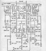
just for you reference here is one Russian ancient SS-Circlotron all BJT amp , where ...
- whole Circlotron OPS is elevated on -36VDC via R14&R15 from stabilized DC source
- VT7&VT9 forms input buffer for input diff. pair VT8&VT10 , where balanced negative VFB is applied via R13&R16,
- VT11&VT12 forms CCS , and VT3&VT6 altogether with VT13 forms I believe limiter or some form of OPS overdrive protection circuit ,but I`m not so sure.
- OPS is VT1&VT4 and drivers are VT2&VT5
- but must say that one well known our DIY member from Russia V.Zaichenko commented to me that this particular amp have way to low OLG and some HQ performance can not be expected .
Is OK if that GNFB network did not influence CCS perfomance ,
about VFA and CFA , personally I never liked the sounds of VFA amps to much ,
in your circlotron configuration output DC offset should be minimum since one half of the amp is completely simetric to another amp half ,
there`s same sex active devices in each amp stage half , if those active devices is initially properly matched DC offset will be automatic at minimum ,
------------------------------------------------
just for you reference here is one Russian ancient SS-Circlotron all BJT amp , where ...
- whole Circlotron OPS is elevated on -36VDC via R14&R15 from stabilized DC source
- VT7&VT9 forms input buffer for input diff. pair VT8&VT10 , where balanced negative VFB is applied via R13&R16,
- VT11&VT12 forms CCS , and VT3&VT6 altogether with VT13 forms I believe limiter or some form of OPS overdrive protection circuit ,but I`m not so sure.
- OPS is VT1&VT4 and drivers are VT2&VT5
- but must say that one well known our DIY member from Russia V.Zaichenko commented to me that this particular amp have way to low OLG and some HQ performance can not be expected .
Attachments
Hi my friend !
Is OK if that GNFB network did not influence CCS perfomance ,
about VFA and CFA , personally I never liked the sounds of VFA amps to much ,
in your circlotron configuration output DC offset should be minimum since one half of the amp is completely simetric to another amp half ,
there`s same sex active devices in each amp stage half , if those active devices is initially properly matched DC offset will be automatic at minimum ,
------------------------------------------------
just for you reference here is one Russian ancient SS-Circlotron all BJT amp , where ...
- whole Circlotron OPS is elevated on -36VDC via R14&R15 from stabilized DC source
- VT7&VT9 forms input buffer for input diff. pair VT8&VT10 , where balanced negative VFB is applied via R13&R16,
- VT11&VT12 forms CCS , and VT3&VT6 altogether with VT13 forms I believe limiter or some form of OPS overdrive protection circuit ,but I`m not so sure.
- OPS is VT1&VT4 and drivers are VT2&VT5
- but must say that one well known our DIY member from Russia V.Zaichenko commented to me that this particular amp have way to low OLG and some HQ performance can not be expected .
My circlotron has for low offset a pot inserted, so we do not need matching, to get balanced.
The schematic you let see do have less supply's but a lot of trouble because of that, like you need for shure a regulated supply.
The feedback in my design is indeed a nice way to automatically balance out offset but still when waring up things can be go wrong a bit, but we see.
I do not now if my circlotron I offer here do sound well or have good performance, I did use cascodes and a diff ccs loaded fasesplitter because these are nice for good audio performance, this driver circuit is also suitable for a normal output with two N-fet transistors, also with some small changes we can use a power J-fet from semisouth, if she still be manufactored.
And maybe because of symetric amp amp ilde current will also be stable, but I have implemented a NTC possibility who can be used later.
regards
- Home
- Amplifiers
- Solid State
- allFET circlotron