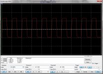
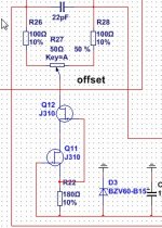
I have found a error in the pcb, the current source transistors need to be j310 types, because simming others give trouble see pictures of 100 Khz wave, one good one fault.
A 2n4392 on top and J112 on bottom give the best. but RF jfet do also very good here, I did sim with the J310 but has a J113 in the pcb schematic, who is not have good working and amp flips out, missing the 4.5 mA current, it sticks then on 1.2 mA giving much to high voltage on R15 and R14.
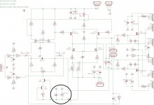
Also we need a little correction on the pcb the gate of Q3 needs to be connect to Source Q4 now it is connected on -15v rail. I did find this out when build up mine.
It is a allfet, so no bipolairs or led.s, jfets are beautifull current sources but need the proper ones, here we did a little mistake, you can for testing using a led and bipolair, your free to do so. I have ordered j310.
scoop is 100 Khz, with the use of the J310 fets, feel Q12 get not hot, I do not think because sim did tell 140mW dissipation.
regards
A 2n4392 on top and J112 on bottom give the best. but RF jfet do also very good here, I did sim with the J310 but has a J113 in the pcb schematic, who is not have good working and amp flips out, missing the 4.5 mA current, it sticks then on 1.2 mA giving much to high voltage on R15 and R14.
Also we need a little correction on the pcb the gate of Q3 needs to be connect to Source Q4 now it is connected on -15v rail. I did find this out when build up mine.
It is a allfet, so no bipolairs or led.s, jfets are beautifull current sources but need the proper ones, here we did a little mistake, you can for testing using a led and bipolair, your free to do so. I have ordered j310.
scoop is 100 Khz, with the use of the J310 fets, feel Q12 get not hot, I do not think because sim did tell 140mW dissipation.
regards
Attachments
Last edited:
I need to order 50R and 100R pots anyway might as well get J310. Is it pin compatible?
Ok I don't feel so bad it does not work first time now.
Thanks
Ok I don't feel so bad it does not work first time now.
Thanks
The 50 and 100 ohms pot is fine, how higher the resistance the weaker the pot, just start again, without output fets active.
the J310 is a RF part, and such did work the best, test the upper one to see it get nog hot because there is the most current over it.
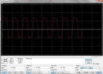
See picture when wrong types are used, and inpact impedance and then the unbalanced input get disturbed.
regards
the J310 is a RF part, and such did work the best, test the upper one to see it get nog hot because there is the most current over it.
See picture when wrong types are used, and inpact impedance and then the unbalanced input get disturbed.
regards
Attachments
Is it working now with J310 or do you still have to order yours? Could 2 more 2sk170's work for the CCS?
Is it working now with J310 or do you still have to order yours? Could 2 more 2sk170's work for the CCS?
I have ordered them, 2sk170 did not work or not well, not all jfets do, but RF types do work oke.
we need total 10 mA and a J-fet who can deliver that.
regards
I may put a BJT and LED to get some sound first and swap back to FET when they come in. Still need to figure out what died in my circuit that stopped bias circuit from responding.
answer lies in zvn4424/2sk170 combination, you say here was 35 volts on the drains of the zvn4424, that is way to high and is a symtom of low current, here you need 25 volts, just remove and use the led/dipolair combination, and put in 10 ma, for 2 x 5 ma in diff amp, giving as al is well, proper voltages on R15 and R14 like 25 volts of something around.
For testing the bipolair current source is oke, need high impedance there so look at that.
use a scope to test signal form.
regards
For testing the bipolair current source is oke, need high impedance there so look at that.
use a scope to test signal form.
regards
So you are saying if I put a BJT and LED where J113 was, then remove ZVN4424 and jumper from D to S?
So you are saying if I put a BJT and LED where J113 was, then remove ZVN4424 and jumper from D to S?
No No
just replace the current source, or wait until the proper jfets arrive.
I have to wait also, and start then, but for quick test just make a current source as you did mention and replace later.
You need 4.5 mA through the two 2sk170, high impedance output (this is why cascade) and keep zeners in the voltages I did advise, otherwise it go wrong, that counts special for the 6.8 volts zener for drivers. (there is 6.2 volts but wrong type in schematic.).
Also we need a little correction on the pcb the gate of Q3 needs to be connect to Source Q4 now it is connected on -15v rail. I did find this out when build up mine.
Can you draw a sketch of what needs to be changed? If G of Q3 goes to S of Q4, where does old S of Q4 go (currently connected to 35v rail via trimmer)? And S of Q3 is connected to 35v rail via trimmer already. That would make both S and G of Q3 connected to 35v rail???
Actually, I think I am confused because the latest diagram you sent me has IRFP9610 as Q3 and Q4. but original schematic has CCS J113's as Q3 and Q4. I think you mean that diagram?
Last edited:
I will wait for parts to arrive and also for you to build the first one and then I can follow in your steps. This amp is tricky and complicated to get running. I have a DC issue in that it won't apply bias correctly. Usually that's a bad resistor value somewhere or a bad Zener diode.
Can you draw a sketch of what needs to be changed? If G of Q3 goes to S of Q4, where does old S of Q4 go (currently connected to 35v rail via trimmer)? And S of Q3 is connected to 35v rail via trimmer already. That would make both S and G of Q3 connected to 35v rail???
Actually, I think I am confused because the latest diagram you sent me has IRFP9610 as Q3 and Q4. but original schematic has CCS J113's as Q3 and Q4. I think you mean that diagram?
It is better to wait until I have the parts and setup the thing because it get confused now, the gate of Q3 sits on the wrong side of R9 180 ohm, needs to be on the other side as I did see on cascoded current sources.
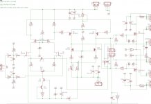
the irf are Q5 and Q6, do you have the right schematic?, I send another who belong to our boards.
I think it did stop working because current for 2sk170 are to high in past, I say that the 180 ohm R9 needs a pot of 1 k first, trim to 10 mA is 5 mA for each side of differential input, the constant current needs high impedance on R23 otherwise you can not feed signal unbalanced, but only balanced, and other things go wrong like feedback, Q2 do not fase shift anymore when gate is on ground when impedance is low, therefore here we need a constant current, like you did with a 47 ohm resistor. maybe a constant current diode who can put out 10 mA can be used, it is several megaohms in impedance and shoult work.
Maybe amp needs to be set up by me, it is a little complicated, and I ahev the stuff to protect against high current. if I not succeed it wil be a circlotronunsucceed. But I am positive it will work.
regards
regards
kees
Attachments
Last edited:
Hehehehe just look and discover why yours do not get idle current in the input section.
What a stupid idiot I am to not see that, it is oke in the sims but not in eagle pcb..
I am curious it the big X sees it, I have give tip in the black cirkel. Did you not here a boom of one of the caps?
Nobody who follow us did see it>?
regards
What a stupid idiot I am to not see that, it is oke in the sims but not in eagle pcb..
I am curious it the big X sees it, I have give tip in the black cirkel. Did you not here a boom of one of the caps?
Nobody who follow us did see it>?
regards
Attachments
Last edited:
Hmm... No boom from my amp. That should have exploded but I think Zener protected because not greater than 15v reverse bias.
I am using same cap that indeed did blow up at 24v when I hooked it up incorrectly in another circuit.
I am using same cap that indeed did blow up at 24v when I hooked it up incorrectly in another circuit.
Last edited:
Hmm... No boom from my amp. That should have exploded but I think Zener protected because not greater than 15v reverse bias.
I am using same cap that indeed did blow up at 24v when I hooked it up incorrectly in another circuit.
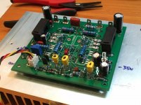
Right, the zener do block high voltage over cap, because it is reversed, you need to reverse both on you pcb and test the J113 again, let me now.
You do have them in your board the wrong way, look at picture, and yes you have total block the idle current for the 2sk170/zvn4424 input stage, who on turn wipe out idle for the rest.
For the rest, I like the pcb design, looks much are correct like not fitting components.
check the zener for shorts.
regards
Attachments
Last edited:
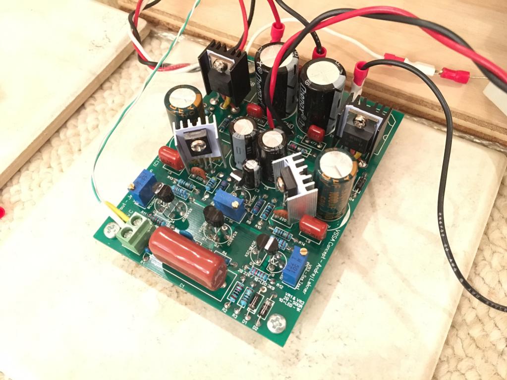
I wonder if the reversed Elco here is what caused the time- delayed non functioning of the bias control - it did not fail right away but slowly shorted out.
I removed the 24v PSU setup for now thinking I was going to wait a while for you to get running first. This does look promising though. Please look for any other errors in meantime and I will try to setup again tonight. Right now I am playing with the 35v rails on another amp - CFH7 again. Needed to hear some music for a change rather than the silence of a Circlotron that won't sing. 🙂
Just made a Jason K VSSA headphone amp with the same IRF610/9610's (note twisted legs 2 & 3) here in lieu of lateral FETs. Current feedback headamp with ability to drive low inpedance headphones and with over probably about 0.5W of power in pure class A mode. 15dB gain seems to work pretty well.
Last edited:
I wonder if the reversed Elco here is what caused the time- delayed non functioning of the bias control - it did not fail right away but slowly shorted out.
I removed the 24v PSU setup for now thinking I was going to wait a while for you to get running first. This does look promising though. Please look for any other errors in meantime and I will try to setup again tonight. Right now I am playing with the 35v rails on another amp - CFH7 again. Needed to hear some music for a change rather than the silence of a Circlotron that won't sing. 🙂
Just made a Jason K VSSA headphone amp with the same IRF610/9610's (note twisted legs 2 & 3) here in lieu of lateral FETs. Current feedback headamp with ability to drive low inpedance headphones and with over probably about 0.5W of power in pure class A mode. 15dB gain seems to work pretty well.
X The zener 15 volts is wrong and the capacitor is wrong, need to flip them both to get 15 volts on current source, then you will see I hope more live.
If the zener do only put 0,6 volts in you have NO current in diff amp and as a result also not in the driver and circlotron. All we be dead and do not sing at all.
Also zeners, put in what sim did advise.
Do you watch out you get no schort with the bolds of the driver fets? the bottom side of the board has voltages close to bolds.
Last edited:
Right now I have 18v Zeners where specified 15v and 6.8v in the middle as you suggest.
Can you show revised diagram with proper orientation of Zener, Elco cap, and Q4/Q3 gate-source change?
Can you show revised diagram with proper orientation of Zener, Elco cap, and Q4/Q3 gate-source change?
Last edited:
Right now I have 18v Zeners where specified 15v and 6.8v in the middle as you suggest.
Can you show revised diagram with proper orientation of Zener, Elco cap, and Q4/Q3 gate-source change?
18 Volts diodes in stead of 15 volts can be used, look if the voltagse are stable.
Just turn around the zener D4 and cap C8 and you are fine, I have already done.
The current source let it what it is and test first. otherwise disconnect gate from Q3 J113 and connect to source Q4 J113 that is all.
regards
If I read this we have done the current source right, but there are more kind of fets usable and also different ones are used.
https://mrevil.asvachin.eu/electronics/modules/
https://mrevil.asvachin.eu/electronics/modules/
- Home
- Amplifiers
- Solid State
- allFET circlotron