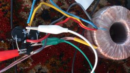
Here is the head amp I burned out the IRF610/9610 on. Immediately after I inserted DAC, I heard a loud click/pop on headphones (connected) then sound was anemic and distorted and clipped/raspy sounding. Replaced the input JFETs and problem still there.
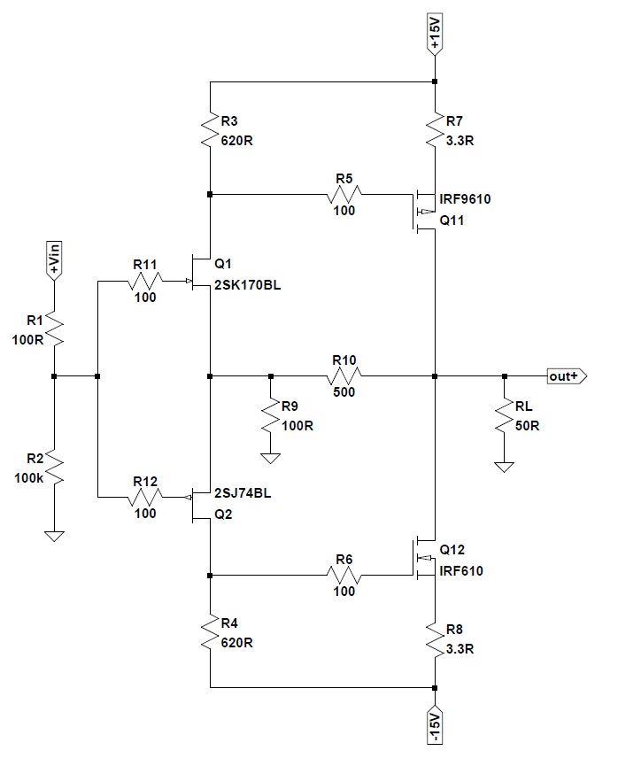
I am not using the R2 100k to GND on input and missing the R1 100R that feeds to the two 100R on the JFET gates. Input is directly coupled to split on 100R's. Also, I am using 2.2R for R7 & R8.
The power supply is regulated with 7815/7915 so is 15v or less. So maybe gate protection diodes not needed as less than 20v.
When this amp works it is very good - super clear low distortion and very neutral.
I just found out that I did not burn my MOSFETs. The MOSFETs damaged the headphone earbuds - which is why it sounded distorted. Anyhow, that amp works great now. One of the best sounding head amps I have heard.
Progress on that amp is now at stage to put in a nice metal case. It's that good.
http://www.diyaudio.com/forums/pass-labs/271926-f5-headamp-72.html
That's a good price on that relay. I guess this amp really needs a DC and short circuit auto protect circuit too. Do you have a simple one to recommend? I have seen several designs in other threads. So many to choose from - just needs to be reliable and simple.
Because it is a mosfet amp a fuse is most of the time enough, I recommed however a clipdetector/dc protection, these are enough of on the internet.
I did also see a idea of servo if dc go walk away what I think it will not as I did see on mine because of inverted fases of output.
The relay is a part of the protection, we need the electronics also, but it alter care, a fuse is enough for short cicuit, mosfets are very immuun to overloads, just blw the fuse, and if one blows the dc protection do the rest.
Mine mosfet hybride with tubes and the 2sk1058 mosfets do just blow the fuse, it is happen already in past multiple times when experiment, never a defective mosfet.
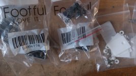
Have received the J310 mosfets, rectifiers (15amps) ceramic insolation pads for irfp450n, things coming in slowly.
I go use two for testing on a board to get the right current from the jfets before installing on the board itselfs.
regards
I go use two for testing on a board to get the right current from the jfets before installing on the board itselfs.
regards
The J310 are fakes, have mail that to ebay, I have get on local store some J310,s and these are oke, get now 4,7mA with 180 ohm, but need some more otherwise the output transistors get not in on state.
If I look to the J310 she are the same like these from the store.
With the chinese J310 I get 20 Microamps, in stead of Milliamps. She are in plastic pack, so maybe damaged also.
If I look to the J310 she are the same like these from the store.
With the chinese J310 I get 20 Microamps, in stead of Milliamps. She are in plastic pack, so maybe damaged also.
Kees, did you try here?
http://www.diyaudio.com/forums/swap-meet/296556-jfet-j174-j310-j105.html
No I did not, but for now I have some and the PN4391 are on his way, and see what happens, maybe a newer and moderner fet is suitable here in future.
I have nog the amp adjusted with the Jfets on place, put them on 10 mA for 5 mA x 2 for the diff amp. There is pretty much differences in the sim or real time, most of the time the model is cause, like mosfet on voltages are different in real time.
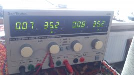
Have my supply adjusted so 2 x 35 volts are present, and I have test not the 10 Khz square, I need to repair the generator who go with sinus and square to 20 Khz. These square is from the cascoded differencial driver who go to the circlotron, it fase shift nicely and voltage is same as on simulation.
For the current feedback line we need for shure keeping lower then 10 mA in loop with full power otherwise the J-fet gets some sweat on his forehead.
regards
Attachments
Last edited:
Hi Kees,
Great progress as usual. Those are very nice clean squarewaves. When you get a chance, can you please post an updated "stuffing" guide showing what component values are now changed and where they go? Also, an updated schematic would be good as well as a picture showing new wiring jumpers to fix the PCB errors.
Thanks,
X
Btw, did the police come to take away your unruly neighbor to jail for irradiating you with a microwave oven yet?
Hi Kees,
Great progress as usual. Those are very nice clean squarewaves. When you get a chance, can you please post an updated "stuffing" guide showing what component values are now changed and where they go? Also, an updated schematic would be good as well as a picture showing new wiring jumpers to fix the PCB errors.
Thanks,
X
Btw, did the police come to take away your unruly neighbor to jail for irradiating you with a microwave oven yet?
Hi X
The police here do nothing about RF abuse, we have PTT Telekom for that, but these people say when I ask that I get sick of that if everything is oke with me and hang up, while hospital allergy specialist say that I have electrostress symtoms, yes crazy country here.
For the pcb, just wait until I get things done, because it changes, as for current feedback met serbian friend is right, it has to be adjusted because it will modulate the CCS when the feedback loop eats to much milliamps, yes X it are just milliamps haha, I try to keep feedback around 5 mA max, and so the CCS needs to supply 15 mA.
I get the supply parts also today, all parts are now here except the PN4391 jfet.
For as we need more mA we can use the modern DN2540 mosfet, these do also works fine and is available. There are of this type also a small TO99 version of 500 mA, then we have no worry about the current feedback CCS pusher haha.
regards
Attachments
Last edited:
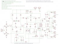
I have adjust the schematic as i use it now, the parts are adjusted and the CCS has a j310 for the PN4391 we need possible some other resistor, but when it just small different we have to do nothing.
X when build it this way it do work, I now go over to the last part, the power output, so when you see a picture 2 then I did fail.
X when build it this way it do work, I now go over to the last part, the power output, so when you see a picture 2 then I did fail.
Attachments

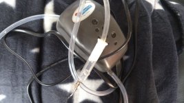
I just use tweezers 😀
I did also but this is very effective and cheap, have a hole in the syringe put vinger on, pick it up put on board and releas my vinger and it is set.
My 50R and 100R trimpots just arrived along with a bag of IRF9610's. I have a bunch of the n channel 610's already. Still waiting for J310 but that will still be a while as from China. I may try a resistor in the meantime.
My 50R and 100R trimpots just arrived along with a bag of IRF9610's. I have a bunch of the n channel 610's already. Still waiting for J310 but that will still be a while as from China. I may try a resistor in the meantime.
Yes try a resistor, I did use 1.5k 1 watt. I go change the board, then you can change it also with some wires so feedback is oke.
The amp has slewing, meaning that when put a 20 Khz square in risetime do slew, this is because the irf 610 is a amplying elelment so input capacity get,s involved, what is 140 pF.
I go look if it can faster by change the input amp on some way or even make a extra cascode on top of the irf 610.
regards
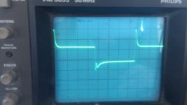
After some testing and measuring I get a nasty peak on the 2.2k R15 and R14 resistors (picture one) Or it is because of the scope probes or it is a issieu with the mosfet capacitances or the fact I do feed unbalanced with one input on ground, I do not now quite well why this happens, maybe also a impedance mismatch or whatso ever, the signal on the output drivers is oke again, so maybe probes do act bad on the resistors.
The square on 20 Khz is in a irfp250n mosfet who is not on supply, so driver see the full capacitance (2.1 nF) of it and it is a little visible in driver output who is not bad..
Recognise somebody this, any tips.
The square on 20 Khz is in a irfp250n mosfet who is not on supply, so driver see the full capacitance (2.1 nF) of it and it is a little visible in driver output who is not bad..
Recognise somebody this, any tips.
Attachments

Hi X
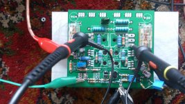
I have succesfully complete the amp, the thermal runaway is present, but I have ceramic insolation plates who do not work well, the mosfet irfp250 who has these get very hot very quickly, this is not oke, so I have to complain to the makers why this is, we need as little as possible thermal resistance, and this is huge.
I can adjust everything fine, it can now on a speaker if I want.
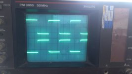
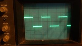
For the square, this is 20 Khz, and have some overshoots who however is not from the amp but from the frequenty generator, as i see now it is very fast.
The runaway however is present, maybe the ceramic plate is the cause but is seems more that it is because of the vertical mosfet, above 500 mA it go accelerate and supply do turn of automatically.
Adjusting the generator so it has little overshoot amp behave a lot better, it is so fast it let through that overshoot coming from the generator.
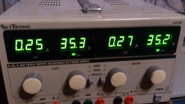
I have just one pot for adjust idle current for both mosfets, as you see there is a slightly different 250 mA versus 270 mA this is because of the mosfets are not machted, this is not
a problem whatso ever because it is just small.
regards
regards
I have succesfully complete the amp, the thermal runaway is present, but I have ceramic insolation plates who do not work well, the mosfet irfp250 who has these get very hot very quickly, this is not oke, so I have to complain to the makers why this is, we need as little as possible thermal resistance, and this is huge.
I can adjust everything fine, it can now on a speaker if I want.
For the square, this is 20 Khz, and have some overshoots who however is not from the amp but from the frequenty generator, as i see now it is very fast.
The runaway however is present, maybe the ceramic plate is the cause but is seems more that it is because of the vertical mosfet, above 500 mA it go accelerate and supply do turn of automatically.
Adjusting the generator so it has little overshoot amp behave a lot better, it is so fast it let through that overshoot coming from the generator.
I have just one pot for adjust idle current for both mosfets, as you see there is a slightly different 250 mA versus 270 mA this is because of the mosfets are not machted, this is not
a problem whatso ever because it is just small.
regards
regards
Attachments


Last edited:
Kees,
Congratulations.
That is some wicked fast slew rate as evidenced by the vertical cliff on the square waves. Looks really good. The thermal runaway will probably be solved with a negative temp coefficient active somewhere in circuit - I guess the IRF610/9610's do not provide that functionality then? I wonder if a simple silicon diode in series with whatever is controlling the bias if placed in thermal contact with MOSFETs could work. You also have provision for the thermistor which at present is bypassed with 10R on my board. Maybe two or more 1N400x's in series here can do the trick?
- Home
- Amplifiers
- Solid State
- allFET circlotron