
With 10R safety resistors in place I could operate for indefinite time at 1.3A idle. The moment I take them out even at 300mA it took maybe 6 seconds. You can hear the MOSFET make a sizzling sound before the sound went dead. Like it was letting off steam in a kettle. 🙂. At 1.3A with no safety resistor maybe 2 seconds. I have lost 2 sets of MOSFETs exploring the boundaries of the thermal runaway.
The runaway in class A is fast so will require either current sensing in the output Source resistor a la Pass M2 or variant of it. Or a BD139 strapped directly to IRFP240 body. Alternatively one can place power current limiting resistors on the input to rails indefinitely to keep current below some level. Not very elegant but seems to work.
The runaway in class A is fast so will require either current sensing in the output Source resistor a la Pass M2 or variant of it. Or a BD139 strapped directly to IRFP240 body. Alternatively one can place power current limiting resistors on the input to rails indefinitely to keep current below some level. Not very elegant but seems to work.
Then mine are oke, it is a fast runout, mosfets are family of a running familie.
using current limiting resistors do kill damping, not a got to.
I go search for a solution, and it is really needed to sense on the mosfet body, or a thin copper plate under the mosfet with on the side a sensing transistor.
for a system like pass we need the resistors and there is no place on pcb for it.
Ok I will try adding a transistor on the body of the MOSFET. Let me know which one to use and where to hook up the flying leads to. Is it simply a BD139 with base connected to collector and placed where NTC pinouy was supposed to go?
Need a npn BD type for use it below in negative but I think a npn reversed will do the same because it is fit as a temp sensor, I hope you can get it between board and mosfets.
make it tight with stuff, the 10 ohm resistor can be there and when it still runs out remove it and test again, put a amp meter in supply line to test and see what happens.
I go do the same. I have use a BD380 who I did have here. If we do not short the pins of the mosfets board can get some higher and it will fit. the resistor 10 ohm is for adjust compensation but do not now it wil work with the transistor, a pot 250 ohm in place of 10 ohm, so you can adjust realt time until idle stays stable is a idea.
Here is another idea about a current stabilization circuit. but then we need cap, I do not want.
regards
Attachments
Last edited:
Can you draw a sketch of how to connect BD139 NPN? TO126 is small enough to fit in there on top of IRFP240.
Can you draw a sketch of how to connect BD139 NPN? TO126 is small enough to fit in there on top of IRFP240.
I have make the holes bigger so bolds can from up through it.
I have another possible cause of the runaway, my irfp are not mosfets butr are igbts??? because I have in past try a amp with this transistors and these did excacly the same, this means the transistors are original but reprinted?
This fast runaway is not normal, a amp with no runaway compensation do run out but that go not so fast, here is maybe more trouble, like the driver section, or just because of it is a circlotron who do double things.
To get this at the bottom, I go change them for others.
The offset voltage however do very good for a current feedback, it stays low.
Attachments
Hmm, I wonder if I have IGBT's as well. Let me install MOSFETs from Digikey with authenticated origins. Although, on yours, they went through a lot of trouble to make the packaging look clean and pristine I suspect you have genuine IRFP's as well.
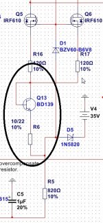
The diagram shows what looks like a simple 2-wire connection from the BD139 strapped to the top of the IRFP240 (btw, the one on the left side seems to go first) with two flying leads. I think the thickness is just perfect fit for the gap that I have.
The diagram shows what looks like a simple 2-wire connection from the BD139 strapped to the top of the IRFP240 (btw, the one on the left side seems to go first) with two flying leads. I think the thickness is just perfect fit for the gap that I have.
Hmm, I wonder if I have IGBT's as well. Let me install MOSFETs from Digikey with authenticated origins. Although, on yours, they went through a lot of trouble to make the packaging look clean and pristine I suspect you have genuine IRFP's as well.
The diagram shows what looks like a simple 2-wire connection from the BD139 strapped to the top of the IRFP240 (btw, the one on the left side seems to go first) with two flying leads. I think the thickness is just perfect fit for the gap that I have.
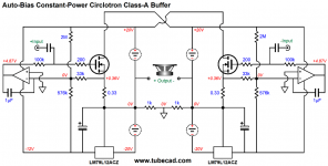
R6 are for degeneration of the emitter if it overcompensate, to big a resitor and we get trouble, need to get enough idle current in driver, it drives irfp,s..
What I not get is how fast the idle runs up, when I start cold with 600 mA it runs to above 1.3 amps in just seconds, as we now the heatup is the cause, but is that so quickly warm? the compensator can never adjust.
this is strange, I did just start cold, can adjust to 500 mA and then it drops slowly so it overcompensates, but when I use a blower it rise within seconds to max amps in my case 1.35 amps to limiting, and stays there.
Possible we get this never stable, so some ideas from readers are welcome here, otherwise we need ot expand circlotron with a driver and use small dif fasesplitter, this one do drive to 2 watts or some more.
I go change the mosfets, see what happens.
X I have serach why it runs away, the irfp,s have quite high transconductance 100 mv do already give a uge idle respons, but the real problem are in the preamp, the J310 do cause a run when she get warm, the current source is not stable, maybe because the 11 mA current she deliver plus some for the feedback network, I think here we need a stronger one, or lower voltage from zener, I go try the last option.
regards
regards
I am running with a resistor where J310 is so I still have problem regardless. Hopefully, the BD139 mounted on the body can respond quick enough to throttle the current when it detects heat. I am a little worried because it seems runaway can happen in 5 to 10 seconds. It seems maybe a varistor on the power supply normally used for controlling turn-on surge may work?
I commend all the detective work you do - making a fresh design from scratch is tough - much of this amp is all rather new. So we see sometimes how much work is needed to get a design adjusted for stability.
I commend all the detective work you do - making a fresh design from scratch is tough - much of this amp is all rather new. So we see sometimes how much work is needed to get a design adjusted for stability.
What I do not understand is why it act like that while the simulation says it is mucho overcompensated, even without Vbe multiplyer.
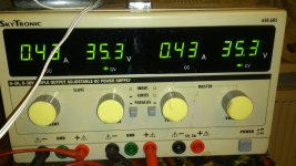
for what the design concerns, it is fun to play with it, but I advice a supply who can be regulated so a run away is not dangerous, in my case it just limit on 1.3 amp can never be higher.
idea over why the sim is otherwise? do we have bad mosfets because a temp runout only happens when the spot in the mosfet get hot whyle the surface is still cold.
I go read stuff so to find it out.
regards
Attachments


I had a 10R resistor and with 25v that was 2.5amp limit. But at 1.3A the system was stable and so never saw the current want to climb higher by itself. That's with no temperature compensator.
The models don't include finite heat transfer rates. Which in reality are finite and can cause localized overheat on the die core like you suggest.
The models don't include finite heat transfer rates. Which in reality are finite and can cause localized overheat on the die core like you suggest.
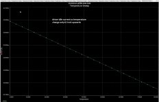
and when only sim the output simulation says it has negative bias respons like a 2sk1058 this do mean I have a wrong model there?. the IRFP250 when get warm lower the idle current, that is fault.
That's definite error on model. HexFET behaves opposite.
I had a 10R resistor and with 25v that was 2.5amp limit. But at 1.3A the system was stable and so never saw the current want to climb higher by itself. That's with no temperature compensator.
The models don't include finite heat transfer rates. Which in reality are finite and can cause localized overheat on the die core like you suggest.
Do you mean the amp stays on 1.3 amps without runout? was that with a resistor in supply lines? or on source for degeneration of that mosfet.
The resistor do ruin the dampings factor, not oke for bass..
regards
Resistor was in supply line - I guess it does limit peak current so bass won't be punchy. Indeed, the 1.3A was stable with resistor in place so that indicates that maybe it's not runaway? Wouldn't it want to peg the max limit at 2.5amps? Hmmm...
Or, maybe it is oscillations that is killing the MOSFET as the 10R is preventing some global oscillation?
Or, maybe it is oscillations that is killing the MOSFET as the 10R is preventing some global oscillation?
Resistor was in supply line - I guess it does limit peak current so bass won't be punchy. Indeed, the 1.3A was stable with resistor in place so that indicates that maybe it's not runaway? Wouldn't it want to peg the max limit at 2.5amps? Hmmm...
Or, maybe it is oscillations that is killing the MOSFET as the 10R is preventing some global oscillation?
Do you have oscilloscope? because in mine amp there is nothing to be seen as oscillations, that resistor is a big one? because it has to let through 2.5 amps.
Then it is better to use a 2sk1058 mosfet, however need pins reversed but temperary on top to see if the driver is the cause of running away.
For me with a transistor it stays on 420 milliamps now, but only with a ventilator it get stable, however when reach 800 mA it go run as hell, when I remove the fan it dorps
to 120 mA again, when cool it it go up again..
I do not understand why, because it meanly the power mosfet who does this, it runs harder then the temeprature do rise and that is very strange because means that the silicon has temperature resistance?, we go try tomorrow the laterals, and the 240 because I have now 250n types. maybe because the mosfets has very low on resistance can play with it.
a lot to do to find out, it is fun.
It is now stable on 470 mA, as I see it is way overcompensated and the reaction of temp sensor way so slow, IRFP250N silicon get already hot before survace do giving a runout.
regards
Attachments
Last edited:
It's a cement filled white ceramic one - rated 10w I think. I have a proper 25w aluminum cased one mounted on a heatsink resistor I could use for long term testing.
I don't know how different IRFP250's are. I will switch to Digikey sourced IRFP240's tonight and see if that helps. I will also add BD139 temp compensator.
It's fun and I learn a lot more when an amp doesn't work the first time.
I wonder if 0.33R Supply resistors on IRFP pins leading to driver would help? Maybe that would dampen oscillations if that was the source?
Last edited:
- Home
- Amplifiers
- Solid State
- allFET circlotron