Good morning all
I hope I'm on the right post to ask my question about my diet of the Aleph X that I build.
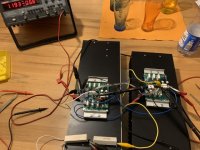
I make separate power supplies for each mono block
with 16 IRFP240 transistors per block.
2 toroidal transformers of 800va per block 2X30v in secondary
with 4 bridge rectifiers RFB 03 from Mister Per Anders.
8 capacitors of 50v 68000uf / CCLCC self of 1.8mh.
at the end of the bridge secondary I have: 42v.
I need 36 V on the connection of my pcb
(I know it will heat up but I have the necessary heatsinks)
my question:
since I'm doing a voltage test at the output of the bridges or the capacitors
once i have connected this 42v to my pcb and i need 36v, will the reduction from 42v to 36v be done once i have connected my pcb?
(because the measurement is taken empty?)
thank you for your answers and my question is clear
(ps: I don't speak too much english it's a google translation)
I hope I'm on the right post to ask my question about my diet of the Aleph X that I build.
I make separate power supplies for each mono block
with 16 IRFP240 transistors per block.
2 toroidal transformers of 800va per block 2X30v in secondary
with 4 bridge rectifiers RFB 03 from Mister Per Anders.
8 capacitors of 50v 68000uf / CCLCC self of 1.8mh.
at the end of the bridge secondary I have: 42v.
I need 36 V on the connection of my pcb
(I know it will heat up but I have the necessary heatsinks)
my question:
since I'm doing a voltage test at the output of the bridges or the capacitors
once i have connected this 42v to my pcb and i need 36v, will the reduction from 42v to 36v be done once i have connected my pcb?
(because the measurement is taken empty?)
thank you for your answers and my question is clear
(ps: I don't speak too much english it's a google translation)
Attachments
![IMG_20200131_122403[1].jpg](/community/data/attachments/726/726695-8ed71c4d899fc5f6b316fcca4ccf029c.jpg?hash=jtccTYmfxf)
![IMG_20200131_122420[1].jpg](/community/data/attachments/726/726720-57c009146dd286d479ee5a759ff82816.jpg?hash=V8AJFG3Sht)
Pass DIY Addict
Joined 2000
Paid Member
Voltage drop will depend on the voltage regulation spec for your transformers and the bias level that you set the amps at. Dropping from 42v to 36v is quite a bit to drop. You may need to introduce some heavily heat sinked high power resistors in your PSU.
You could hook up an incandescent lightbulb (or several in parallel) across your power supply to see how it reacts under load. The incandescent lightbulbs are rated for 230V AC, so they can easily withstand the PSU voltages and don't need heatsinks. The cold resistance of a 100W 230V bulb should be 20 - 40 Ohm (easy to measure with a voltmeter), so you will not short the PSU.
unloaded rectifier block/cap ban will give you Vdc = 1.41 x Vac
in real life , with heavy loaded rectifier block/cap bank , multiplier is in vicinity of 1.25
example - regular FW amp is having 2 x 18Vac secondaries , resulting in approx. 2 x 22V5dc rails
in real life , with heavy loaded rectifier block/cap bank , multiplier is in vicinity of 1.25
example - regular FW amp is having 2 x 18Vac secondaries , resulting in approx. 2 x 22V5dc rails
Pass DIY Addict
Joined 2000
Paid Member
Light bulbs are an excellent idea! Just calculate the total power draw of your completed amp (rail voltage * 2 * bias current) and parallel incandescent bulbs until you are there.
Thank you for your answers
they helped me a lot,
I contacted a friend in France who comes to this forum it's "Nar"
he gave me a good solution
so theoretically
2x30v in secondary x 1.25 will give me once connected
2x37.5 dc in rail
With a Tritec of 0.419 ohm per rail, V drop at 8 amps:
U = R x I = 0; 419 x 8 = 3.352V
Pw dissipated at 8 amps:
P = U x I = 3.352 X 8 = 26.816W
so ok for the Tritec, I think, it will heat up.
I would have to do the real test by connecting everything to see the temperature
Alternative: resistance 0.39 ohm / 50W in golden radiator,
it will heat too ... if you find 0.39 ohm / 100W it will be lukewarm ...
So, you should have (30 x 1.25) - 3V on chokes or R roughly, that is 34.5 / 35V rails. Correct for mounting
this is one of the solutions that suits me
the incasdecentes lamps were good too
he extreme solution if I can say would be
the secondary sequence of the toroidal transformer
if i can avoid ....
Last edited:
man , what you're building with 30+ Vdc rails ????
did you calculated power dissipation and resulting power , you'll get with that voltage ?
and , in that case - to execute it properly , you need at least twice outputs ....... 16/channel is not nearly enough for Monster
did you calculated power dissipation and resulting power , you'll get with that voltage ?
and , in that case - to execute it properly , you need at least twice outputs ....... 16/channel is not nearly enough for Monster
sorry for the late response
indeed, the dissipation would be too great with 36v rails with an 8A bias adjustment (500mA per transistor)
about 576W dissipated per block.
too important .
I change the project and I take a secondary 16V transformer
which will give me about +/- 22v on pcb
and 12 mosfets per block bias adjustment in 6A / 7A (500 or 600mA per transistor) 264W if adjusted to 6A and 308W if adjusted to 7A
therefore 132w or 154w per side, there the project is viable and peaceful for several years because I have the heat sinks they allow.
Voltage 22
Bias 6
Ac current gain 50%
Number of fets 12
Peak current 6
Power 8 Ohms (RMS) 100
Power 4 Ohms (RMS) 72
Power 2 Ohms (RMS) 36
Dissipation for one channel 264
Dissipation per fet 22W
Transform standard secondaries 16.10
Voltage 22
Bias 7
Ac current gain 50%
Number of fets 12
Peak current 7
Power 8 Ohms (RMS) 100
Power 4 Ohms (RMS) 98
Power 2 Ohms (RMS) 49
Dissipation for one channel 308
Dissipation per fet 26W
Transformer secondaries standard 16,10
on power configurations
in CCLCC OR CCRCC
what would be the value of L or "R (in 50 or 100w)"
thank you
in CCLCC OR CCRCC
what would be the value of L or "R (in 50 or 100w)"
thank you
Pass DIY Addict
Joined 2000
Paid Member
Aiming for 22v rails is MUCH more reasonable and will result in a chassis that you can actually lift and carry around for maintenance in 10-15 years.
As for filtering, my PSU uses a 1000VA transformer with 19vAC secondaries. After rectification and CRC filtering, I get about 22vDC for the rails. The first C is about 50,000uF, R is a 0.07ohm 50w gold bodied aluminum sink attached to the floor of the chassis and the final C is 200,000uF. I get about 10-20 mV of ripple on an 8A current draw.
You want to keep any resistance in your power supply low, aiming for somewhere near 0.10ohms (especially with a high current draw). If heat dissipation of your resistors is too high (check spec sheet) you can take two larger resistors, say 0.15ohms and parallel them for 0.07ohms overall.
Hello,
I am in the last test phase for the 18 Aleph-XJ for our small „amplifer anonymous“ group 🙂
Hopefully I can deliver some nice pictures the next months. Or is it preferred to open a new threat for that?
Regards, Jean-Claude
I am in the last test phase for the 18 Aleph-XJ for our small „amplifer anonymous“ group 🙂
Hopefully I can deliver some nice pictures the next months. Or is it preferred to open a new threat for that?
Regards, Jean-Claude
Attachments
if you're shy , you'll post nothing
if you're less shy , you'll post one or two pictures , here in thread
if you're even less shy , you'll open new thread , write several posts , post plenty of pictures , and brag around how amp is great and great sounding and best ever made and that you're greatest DIY-er in Germany and maybe even in Eu.
guess - which way we prefer ?
ZM , Greatest DIY-er in The World , except De and Eu
Okay, I think I understood...
seems that its unavoidable to start a new threat 😀
Regards, J-C
seems that its unavoidable to start a new threat 😀
Regards, J-C
- Home
- Amplifiers
- Pass Labs
- Aleph-X builder's thread