Haha, you're absolutely right. Only thing that bothers me is that I don't understand why it doesn't work with the standard values. But I'll lower r24 for now and will see what happens... Thanks!
Jan,
look at post #2561, here's a pdf with a dc-servo where the absolute dc offset behaviour ist described. Maybe this helps to understand the mechanism.
William
look at post #2561, here's a pdf with a dc-servo where the absolute dc offset behaviour ist described. Maybe this helps to understand the mechanism.
William

Thanks William (and of course Papa, Grey hifizen ánd Eric for his amazing write up).
Saved the day and thanks for the pdf of a dc servo. First amp up and running again. Always a great feeling!
Saved the day and thanks for the pdf of a dc servo. First amp up and running again. Always a great feeling!
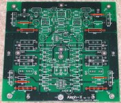
Okay, probably a dumb question but nevertheless here we go. Build two monoblocks as per Grey's lower power design (green boards from hifizen) 15V 4.5A. Next step is to parallel the output devices to up the power (yup increase rail and bias as well). However, I would really like to use the output connectors for Q1,2,10,11 as I've used screw terminals for the wires and I like the flexibility of changing stuff fast🙂.
The question is, should I jumper the source resistors on the PCB to be able to use the original output connectors or will this screw stuff up or anything else I'm missing that is not okay? I've attached a drawing as well just to be sure (I have the gate resistors already off board hence the red jumpers as well).
Any help is greatly appreciated!
Jan