Yes,
if you cut out the 4k7 and increase the LTP-CCS current by the 4k7 current, its the same 😉
if you cut out the 4k7 and increase the LTP-CCS current by the 4k7 current, its the same 😉
that board's a blast from the past! 🙂Yup, Aleph X headphone amp with Jfet frontend and FQP3N30 ccs/outputs. For now I have it biased at 0.5A with +/-15V rails. With the X'd circuit that's 30W dissipation per side.
I have yet to listen to the amp, the setup is still very experimental. Next I'll be adding a DC servo I suppose. The semis are tightly matched and track really well thermally, so in theory it should work without a servo, but it's an easy enough tweak and brings some peace of mind.

Amazing. So neat, so professionally done! 👍Here some additional pics from build-up
JCN, I went back through your posts regarding the Aleph X today. Beautiful work. How have the 16 monoblocks done so far now that it is a few months later?
Hello,
they run fine since nearly 3 years now. 1 had a fault because of a faulty mica pad in the LTP-CCS.
I must admit that mine run in low-power bias at 95% of the time because of power consumption. 700W / stereo at full throttle is a little too much for me in the actual „green“ world with expensive electricity. But a friends amps run at 100% with no problem.
Sound wise they convince since day one, but we have annother project in work, giving a hard match for the aleph-JX with a more conventional output stage running at lower bias.
Regards J-C
Dzień dobry, chciałbym wiedzieć, czy można kupić pcb do aleph x w nowej wersji lub czy mogę dostać gebbers do drukowania pcb. Dziękuję i pozdrawiam.

To jest anglojęzyczne forum. Jeśli chcesz publikować w innym języku, dołącz tłumaczenie.
Dziękuję.
This is an English speaking forum. If you wish to post in another language, please include the translation.
Thank you.
Google Translate:
Good morning, I would like to know if it is possible to buy pcb for aleph x in the new version or if I can get gebbers for pcb printing. Thank you and best regards.
Hello,
I have the following question about the Aleph X boards. Is there anyone in the forum who can sell me a few (one pair) unused PCBs?
Thanks,
Tom
I have the following question about the Aleph X boards. Is there anyone in the forum who can sell me a few (one pair) unused PCBs?
Thanks,
Tom
Pass DIY Addict
Joined 2000
Paid Member
I figured you'd still have a small stack of boards, William!
Tom, once you get your boards, have a look at my web page for the Alexph-X (https://sites.google.com/bucknell.edu/ericshometheater/erics-home-theater/aleph-x-clone-amps). I haven't touched it in years, but it still has a ton of great information about building this amp and my set of amps is sill running strong.
Tom, once you get your boards, have a look at my web page for the Alexph-X (https://sites.google.com/bucknell.edu/ericshometheater/erics-home-theater/aleph-x-clone-amps). I haven't touched it in years, but it still has a ton of great information about building this amp and my set of amps is sill running strong.
Hi Eric,
I bought 4 boards just in case….. with an Aleph J and F5 waiting to be build I don’t think I will need them anymore.
william
I bought 4 boards just in case….. with an Aleph J and F5 waiting to be build I don’t think I will need them anymore.
william
Dear All,
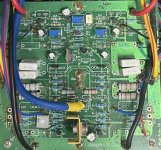
I am trying my luck to check if anybody still has the Aleph-X pcb boards to spare. I am planning to build a monoblock pair with more output mosfets.
The particular PCB board as in attached photo.
Appreciate if you can drop me a note if you have spare boards.
Thank you.
I am trying my luck to check if anybody still has the Aleph-X pcb boards to spare. I am planning to build a monoblock pair with more output mosfets.
The particular PCB board as in attached photo.
Appreciate if you can drop me a note if you have spare boards.
Thank you.
Attachments
Dear Mike,
Thank you for your quick replay and the information. I will contact him to check.
Thank you
Thank you for your quick replay and the information. I will contact him to check.
Thank you
Hi guys,
Rediscovered the aleph-x and thought to redo my stereo amp and make two monoblocks.
I have triple checked all my resistor values, diodes in right direction and working and matched Q5/7, Q1/10, Q2/Q11 and r6/41 and r23/25.
However, I keep getting an absolute DC which gets stuck at about 8.8V without dropping any further, relative DC is about 220mV with VR1,2 and 3 all at 0R.
- voltages across the Qs
Also checked the MPSA18s:
Q4/9 both the same Ve=-15, Vb=-15, Vc=-10, Q3/8 are roughly the same Ve=8.5, Vb=9.1, Vc=14
What am I missing here? Could this all be from a lower voltage across the zener? Or could it be that the MSPA18s are faulty? Measured all IRF240s and irf9610s and they seem to be ok.
Any help is greatly appreciated!
Jan
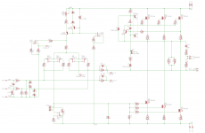
Attached the used schematic
Rediscovered the aleph-x and thought to redo my stereo amp and make two monoblocks.
- used the rev1 board from hifizen (the green board)
- lower power version from grey (15V rail, 4.5A bias, 1 IRF240 per quadrant)
- used all the values given by hifizen with the only difference I changed r46/47 to 10k instead of 4.7k (see attached schematic)
- as for the options: jumper across Q12a, jumper across J1a, installed D1a (zener), installed the optional C2 and C4.
- PSU is a basic CRC 94mF/0.6/100mF with a 625VA 2x15V secondary, unloaded the PSU will give 18V loaded it gives 15V, ripple about 10mV (matches with PSUD simulation)
I have triple checked all my resistor values, diodes in right direction and working and matched Q5/7, Q1/10, Q2/Q11 and r6/41 and r23/25.
However, I keep getting an absolute DC which gets stuck at about 8.8V without dropping any further, relative DC is about 220mV with VR1,2 and 3 all at 0R.
- Voltage across voltage reference zener d1 is 8.7V--> seems a bit lower than expected as it is a 9.1V zener
- Voltage across R23/25 is 4.97/4.90V-->seems a bit high would expect more in the order of 4V not sure why this happens (zener?)
- Voltages across R5/6 and R40/41 are around .485/.421V and .469/.406V
- VR1 and VR3 give me a bit of freedom to finetune the voltage drop R5/6 andR40/41
- Turning VR2 CCW (increase the resistance) will increase the absolute DC (as expected as it is still a positive absolute DC)
- voltages across the Qs
| Q1 | Q10 | Q2 | Q11 | Q5 | Q7 | Q6a | ||
| G | 15 | 15 | -10 | -10 | 1.7 | 1.7 | 6.5 | |
| D | 15 | 15 | 9.7 | 9.75 | -10.4 | -10.4 | 5.5 | |
| S | 10 | 10 | -15 | -15 | 5.3 | 5.4 | 10.4 |
Also checked the MPSA18s:
Q4/9 both the same Ve=-15, Vb=-15, Vc=-10, Q3/8 are roughly the same Ve=8.5, Vb=9.1, Vc=14
What am I missing here? Could this all be from a lower voltage across the zener? Or could it be that the MSPA18s are faulty? Measured all IRF240s and irf9610s and they seem to be ok.
Any help is greatly appreciated!
Jan
Attached the used schematic
Attachments
Hi Jan,
did you change R23/25? Bias seems to be around 24mA through the input diff pair. I think this must be higher. You could lower R24 to get more bias through the diff pair or increase R23/25 to get a higher voltage at the gates of Q2/Q11. This will lower absolute DC offset.
There are probably a few more resistors that need to be changed because of the 40% drop in rail voltage.
Hope this helps,
William
Hi William,
Thanks for your response. R23/25 are the original values (392), but please correct me if I'm wrong. But with about 5V instead of 4V across R23/25 you get a total of 24mA bias, so 12mA bias per 9610 which is only 2mA off compared to the 10mA bias @ 4V. Or am I missing something here (again🙂)
I tried simulating the PSU with PSUD and saw the same when not loading the PSU (have omitted to mention I have a pretty large bleed resistor in the PSU at about 50 Ohms so I wouldn't shock myself working with an open case🙂, and with only that load I simulate about 19V on the rails).
- Home
- Amplifiers
- Pass Labs
- Aleph-X builder's thread