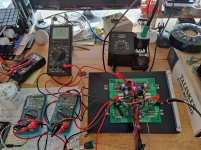
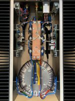
Yup, Aleph X headphone amp with Jfet frontend and FQP3N30 ccs/outputs. For now I have it biased at 0.5A with +/-15V rails. With the X'd circuit that's 30W dissipation per side.
I have yet to listen to the amp, the setup is still very experimental. Next I'll be adding a DC servo I suppose. The semis are tightly matched and track really well thermally, so in theory it should work without a servo, but it's an easy enough tweak and brings some peace of mind.
I have yet to listen to the amp, the setup is still very experimental. Next I'll be adding a DC servo I suppose. The semis are tightly matched and track really well thermally, so in theory it should work without a servo, but it's an easy enough tweak and brings some peace of mind.
Attachments
Which value are you using on the source of the jfets?
I'm using 1k ohm when installing "B" grade jfets from linear systems. Wondering if I'm far off.
I'm using 1k ohm when installing "B" grade jfets from linear systems. Wondering if I'm far off.
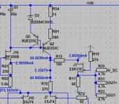
I arrived at 1k source resistors with Toshiba 2SJ74BL jfets. The CCS is pushing about 11mA though the differential pair, and the Vgs of the output Fets is at 5.8V.
Initially I had trimmers in place of the source resistors and tried different operating points. The FQP3N30 need a bit more Vgs voltage to turn on, so 1k with about 11mA through the differential pair combined seems reasonable. In the pic you can see the pots. CCS, bias, AC current gain, source resistance. Seven interacting pots, that was fun to set up.
Initially I had trimmers in place of the source resistors and tried different operating points. The FQP3N30 need a bit more Vgs voltage to turn on, so 1k with about 11mA through the differential pair combined seems reasonable. In the pic you can see the pots. CCS, bias, AC current gain, source resistance. Seven interacting pots, that was fun to set up.
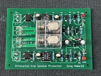
I had built the AlephX before and for speaker DC protection I had used standard DC protection circuit meant for non differential amplifier outputs. For that I had to use two separate protection boards driven by two independent supplies so that I can connect the (-) and (+) speaker output to the protection board with the (0) or Gnd supply floating. Reason being for differential output amplifier the DC monitoring is across the (-) and (+) speaker outputs which are both “hot”. DC monitoring is not reference to ground. One solution is to use a differential input pair for monitoring. What I have recently designed is using opto coupler inspired by recent output stage biasing scheme used in Pass Labs forum.
Here is my completed design for sharing if anyone is interested. It’s also my first attempt sending the design to a fabrication house to produce the PCB which works out quite well.
Here is my completed design for sharing if anyone is interested. It’s also my first attempt sending the design to a fabrication house to produce the PCB which works out quite well.
Attachments
schm?
I remember EUVL designed protection circuit dedicated to bridged amp construction
simple and sweet
I remember EUVL designed protection circuit dedicated to bridged amp construction
simple and sweet
Oh, wish I seen it first. Haha. Let me search. Maybe if somebody knows the thread may be kind enough to share it. Thanks.
Maybe EUVL could be kind enough to share it. Save me the time to search for it. ThanksOh, wish I seen it first. Haha. Let me search. Maybe if somebody knows the thread may be kind enough to share it. Thanks.
Ok found it. Thanks tonZenMod for the info. Here it is :
XEN Balanced Speaker Protection Public 131003
XEN Balanced Speaker Protection Public 131003
Here is the clickable link
http://xen-audio.com/documents/f5x/XEN Balanced Speaker Protection Public 131003.pdf
http://xen-audio.com/documents/f5x/XEN Balanced Speaker Protection Public 131003.pdf
Hello,
after all these years… is there still some interest that I present my „final Aleph-JX“ here in this forum? I think there is a nice solution for the common-offset-problem.
Regards, Jean-Claude
after all these years… is there still some interest that I present my „final Aleph-JX“ here in this forum? I think there is a nice solution for the common-offset-problem.
Regards, Jean-Claude
Pass DIY Addict
Joined 2000
Paid Member
Yes!
Still using my Aleph-JX and curious to hear your solution although I don't have the common-offset-problem.
Still using my Aleph-JX and curious to hear your solution although I don't have the common-offset-problem.
Okay… tomorrow! I forgot the stick with the whole story at work 🙄
But is it preferred to write it here or in a new threat?
Edit: Spoiler in the „pics of you pass amp“ threat 😉
Regards, J-C
But is it preferred to write it here or in a new threat?
Edit: Spoiler in the „pics of you pass amp“ threat 😉
Regards, J-C
Hello,
here I like to present my Aleph-XJ.
At first, a little history: Around 2000 my boss told me about his 1-stage amplifier at the christmas-party and draw the schematic on a napkin.
So I started research about this amplifier and build my first ZEN-prototype. Then I went further and decided to build-up an Aleph-30. During Spice-Simulation I started modelling a symmetrical version with two outputs - but had the unavoidable trouble with Common-Mode DC and the project was on hold.
Then some research later I found the schematic of G.Rollins in the web and the discussion at diyaudio.com.
Therefore me and two collegues decided to build-up 3 versions of it. Since no one knew how it will perform, we were at little "economical", and at the end we had a well sounding, but very hot running amplifier due to too small heatsinks. 75° is really hot! And some hum of the (also too small) toroid.
It was +/- 18V, 4A total, 3 Mosfets per quad. And 500VA for stereo. It was the standard circuit with a servo for common mode offset regulation. This was 2005 and then my childs prevented me from building up more amps.
But from the beginning there was the plan to build up the "real stuff" one day. The other drawback of the amp was that it will perform significantly better with a symmetrical input source. As I measured Uout+ and Uout- with a RCA source there were different voltages at the two outputs because of a non-ideal performing input stage due to the "McMillan resistors" (2*4k7) which naturally mess up the common-mode rejection. Instead of doing some work on linearizing the temperature behavour and rising the resitors I planned to get rid of the problem completely.
So there are the reqirements for version 2:
This was realized by the following technical solutions:
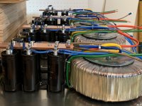
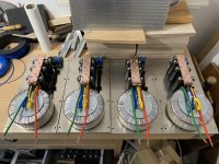
My collegues from the "amplifier anonymous" - group were excited about the concept, so we decided to built-up 18 (!) monoblocks of it. Nice if you get delivery of 18 800VA toroids, 32 heatsinks, 108 36mF capacitors... 🙂
After a lot of planning, ordering, soldering,... we have built-up 16 of them. 2 are still on hold. There was no problem during built-up, all 16 worked fine. They sound wonderful, significantly better than the first version. And no trouble with common-mode-DC with even perfect behaviour when supplied by a single-ended source.
Annother nice feature is a bias-switch at the front to switch between 2A - 4.8A - 6.2A. Due to servo for common-DC there is no problem with the 3 operating points. The low-bias is fine for background listening at ~35°C heatsink temperature, maximum bias gives ~60°C. Input can be RCA/XLR and DC/AC-coupled (both selected by a jumper), I run it DC-coupled without any trouble. Output power is ~120W @8R and ~100W @4R.
So I would like to stick my neck out and call it "the best aleph-X" amplifier" 😎
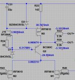
There is a new option in mind which is a simpler and probably even little better working solution - by a modified circuit and using of an BC560C instead of the K170. This will be a option for upgrading my existing Aleph-X because all is needed is to add a BC560c and a zener. Perhaps there is some interest of other owners to give it a try.
Attached I have 2 versions of the input stage, the "CCS_K170" is the version running in the 16 Amplifiers, the "CCS_BC560" can be a simple add-on for standard-Aleph-X with IRF9610 Mosfets (Zener Voltage must be set ~1.5-2V above the node voltage of the 9610-sources).
The pdf are the measurements, in german but I think the graphs are self-explaining.
Regards, Jean-Claude
here I like to present my Aleph-XJ.
At first, a little history: Around 2000 my boss told me about his 1-stage amplifier at the christmas-party and draw the schematic on a napkin.
So I started research about this amplifier and build my first ZEN-prototype. Then I went further and decided to build-up an Aleph-30. During Spice-Simulation I started modelling a symmetrical version with two outputs - but had the unavoidable trouble with Common-Mode DC and the project was on hold.
Then some research later I found the schematic of G.Rollins in the web and the discussion at diyaudio.com.
Therefore me and two collegues decided to build-up 3 versions of it. Since no one knew how it will perform, we were at little "economical", and at the end we had a well sounding, but very hot running amplifier due to too small heatsinks. 75° is really hot! And some hum of the (also too small) toroid.
It was +/- 18V, 4A total, 3 Mosfets per quad. And 500VA for stereo. It was the standard circuit with a servo for common mode offset regulation. This was 2005 and then my childs prevented me from building up more amps.
But from the beginning there was the plan to build up the "real stuff" one day. The other drawback of the amp was that it will perform significantly better with a symmetrical input source. As I measured Uout+ and Uout- with a RCA source there were different voltages at the two outputs because of a non-ideal performing input stage due to the "McMillan resistors" (2*4k7) which naturally mess up the common-mode rejection. Instead of doing some work on linearizing the temperature behavour and rising the resitors I planned to get rid of the problem completely.
So there are the reqirements for version 2:
- More power
- More cooling
- More power supply
- No McMillan resistors in the existing form
- Linearization of the temperature behavour.
- JFet input stage
This was realized by the following technical solutions:
- Monoblocks with 2 heatsinks per channel (Fischer SK650)
- Rail voltage of 24-25V to minimize capacitance of the Mosfets as recommended by N. Pass.
- Bias 6.2A total for maximum power at ~6R
- Mosfets chosen 3 per quad (~25W / each), IRFP044N due to less cap as 044 without N.
- Replace the IRF9610 by 2SJ74, 2 in parallel, 5mA per J74 requires no cascoding.
- The signal from the McM Resistors is transformed into a high impedance current signal. Realized by only adding a 2SK170 in gate-circuit between the correction-signal from the McMillan-Ristors plus DC-Servo and the input stage. The K170 then feeds the signal as a current source with high impedance, with the result that the circuit reacts as when the McMillan resistors were in the range of hundreds of kOhm.
- Own PCBs, with common-mode servo and differential-DC adjustment.
- New CCS of the input tail with better temperature linearity
My collegues from the "amplifier anonymous" - group were excited about the concept, so we decided to built-up 18 (!) monoblocks of it. Nice if you get delivery of 18 800VA toroids, 32 heatsinks, 108 36mF capacitors... 🙂
After a lot of planning, ordering, soldering,... we have built-up 16 of them. 2 are still on hold. There was no problem during built-up, all 16 worked fine. They sound wonderful, significantly better than the first version. And no trouble with common-mode-DC with even perfect behaviour when supplied by a single-ended source.
Annother nice feature is a bias-switch at the front to switch between 2A - 4.8A - 6.2A. Due to servo for common-DC there is no problem with the 3 operating points. The low-bias is fine for background listening at ~35°C heatsink temperature, maximum bias gives ~60°C. Input can be RCA/XLR and DC/AC-coupled (both selected by a jumper), I run it DC-coupled without any trouble. Output power is ~120W @8R and ~100W @4R.
So I would like to stick my neck out and call it "the best aleph-X" amplifier" 😎
There is a new option in mind which is a simpler and probably even little better working solution - by a modified circuit and using of an BC560C instead of the K170. This will be a option for upgrading my existing Aleph-X because all is needed is to add a BC560c and a zener. Perhaps there is some interest of other owners to give it a try.
Attached I have 2 versions of the input stage, the "CCS_K170" is the version running in the 16 Amplifiers, the "CCS_BC560" can be a simple add-on for standard-Aleph-X with IRF9610 Mosfets (Zener Voltage must be set ~1.5-2V above the node voltage of the 9610-sources).
The pdf are the measurements, in german but I think the graphs are self-explaining.
Regards, Jean-Claude
Attachments

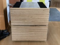
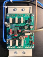
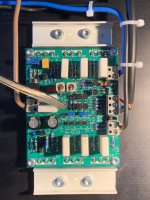
Here some additional pics from build-up
Attachments
-
 8A3DA5A0-1623-45B0-88D5-0DC9CC9CA753.jpeg536.1 KB · Views: 370
 -
 7F96F78E-9FA6-4991-81F0-40FDDB683A46.jpeg517.9 KB · Views: 358
 -
 5552C80E-D8C5-4831-94E1-8BF5712B480C.jpeg544.2 KB · Views: 362
 -
 1DF7C43A-4B19-40D1-8B12-B4155CF69D3A.jpeg471.6 KB · Views: 358
 -
 1D95D719-8ED4-4DEE-A7D2-514C1827B742.jpeg437.8 KB · Views: 368
 -
 B392BD1D-0F85-42E9-AEDD-C1CC2E2F351A.jpeg501 KB · Views: 352
Hi Jean-Claude,
do you have a bit bigger view of the schematic? Using different part numbers makes it a bit difficult for me to read(still used to R46/47 as McMillan resistors), and there seem to be a few more changes to the current source of the original 2003 circuit. Do you need the McMillan resistors at all when using a servo? Mine were around 33k even before I put in a servo and probably can be made even higher (just couldn't find the time to try).
Regards,
William
Hi,
yes the CCS is completely new for more stable current. In my schematic, I add 3 components, OUT+, OUT- and Servo (U_DC). I kept the „McMillan“ component because this signal reacts instantly with no delay at start-up. The Servo is only for fine-adjust and it will allow a current-switch for „background listening“ without having different DC at different settings.
The circuit for sure will also work with servo only or out+/out- only.
The key figure in my schematics are the transistors feeding the input tail with high-impedance current instead of several kOhms. So the Amplifier behaves as when using 100k McMillans (up to several MOhms with the BC560 version), combined with total stable DC condtions because the Resistors for the correction signal can be in the range of 2k2 without harm. This all by only adding a single Transistor and Diode/Resistor.
I will send a bigger schematic later…
Regards, Jean-Claude

I‘ sure your are… very nice amps 👍
To your Servo: I think you load the LTP with 1k5 + 4k7. Same as two ~12k McMillan Resistors. Isn‘t it working to replace the 4k7 by a CCS? Or perhaps insert the current directly into the CCS of the LTP (?)
Regards, J-C
To your Servo: I think you load the LTP with 1k5 + 4k7. Same as two ~12k McMillan Resistors. Isn‘t it working to replace the 4k7 by a CCS? Or perhaps insert the current directly into the CCS of the LTP (?)
Regards, J-C
it's really just additional CCS to basic LTP CCS
same as yours
it was revelation years ago, term wise, when I read how Pa declared resistor as CCS, even if poor one
🙂
same as yours
it was revelation years ago, term wise, when I read how Pa declared resistor as CCS, even if poor one
🙂
- Home
- Amplifiers
- Pass Labs
- Aleph-X builder's thread