Just get the bigger caps.
People go on and on about the fact they can here distortion at crazy low levels, and discuss effects of IMD etc.
Well you might not hear the psu hum from the supply, but this interacts with the audio signal and produces IMD, which may be audible (smearing).
So a quieter supply ie more caps is technically better.
The other effect will be that you will get lower output impedance at 20 Hz with more caps.
Who knows how much of it is audible, but the time spent building an amp is worth a lot more to me than trying to save a few dollars by buying smaller caps.
It's your choice
They seem really nice. A lot of capacitance in 35mm X 52mm package.
Make sure you go big in chassis size with 2 X 400VA transformers.
Try to position the transformers and the PS PCB in such a way to minimise the AC wiring length, as well as DC hook-up wiring length.
That’s a super clean set up...how/where did you run the torpid secondaries to the diodes and why not flip the power supply to put the AC diodes closest to the transformer?
The transformer wiring runs underneath the transformer mounting plate and power supply PCB.
The secondaries' wiring runs from the transformer to the front of the amplifier, because the length of this low voltage AC wiring is not important (it is least harmful to the amplifier operation/specifications); what IS very important is the length of the DC wiring. By orienting the power supply PCB in this way, I have managed to reduce the DC wiring to the bare minimum.
The CL-60 is soldered directly to the IEC filter legs. There is plenty of room for it to run reasonably cool (determined by the nominal current that runs through it anyway).
The mains wiring length is only 10cm.
Oh crap it's 5:23am.
I better sleep now.
I have issues.
hahahahaha
I did not think you ever slept
 🙂
🙂Just get the bigger caps.
People go on and on about the fact they can here distortion at crazy low levels, and discuss effects of IMD etc.
Well you might not hear the psu hum from the supply, but this interacts with the audio signal and produces IMD, which may be audible (smearing).
So a quieter supply ie more caps is technically better.
The other effect will be that you will get lower output impedance at 20 Hz with more caps.
Who knows how much of it is audible, but the time spent building an amp is worth a lot more to me than trying to save a few dollars by buying smaller caps.
It's your choice
I found these to work quite well at a reasonable cost:
380LX333M035A052 Cornell Dubilier - CDE | Mouser
Low ESR, 35V, good microfarads per dollar, only rated at 3000 hours, though.
For the small transistors, am I correct that, when looking at the pins, with the front (flat) side up, the order of the pins is, left to right, C B E?
I can't tell you how happy I am to find this build and page. I especially love the attention to orderly detail--with solid understanding of grammar and syntax. While I appreciate the previous post (2013), it's a disorderly mess.
Greek
I really, really appreciate 6L6's work and passion over the years to populate and advance this hobby. But the simple fact is that he is speaking/typing Greek to me.
If I asked you to reply to me and this comment with a triple, introductory adverbial phrase in the first sentence and a noun clause as the subject of the second sentence, and a right-branched, compound, complex third sentence with active verbs and no subject complements in the predicate, would you even know what I'm talking about--even if you Googled it?
The point of this thread is that I don't know those words that 6L6 used in his build thread, and he brought them over here (with good intentions!) without explanation. They impart no meaning onto me. That goes for a lot of the comments that start on page 3-4 of this thread.
Look, I don't even know what a snubber is. What is a variac? What do you even mean by bulb tester? What even is a diode and a rectifier and a bridge, and how should I know to do it this way versus another way?
A few weeks ago, I bought the AJ amp boards and BOM and chassis and thought I was good. I recently discovered I needed a PSU, and then all these measurements and... JFC... I want to throw in the towel. And while I'm a noob, I've successfully built other DIY hum-free, SET tube monoblocks.
Appreciate ya'll, but you need to put yourself back to 3rd grade to explain these things that are fundamental to you that we haven't learned yet (not fundamental to some of us). That's the point of THIS thread. Really need more definition and less "tell."
This is where *I* am coming from and, presumably, others, too.
Correct.
Also understand that a populated one click cart will require almost constant maintenance and updating as parts go in and out of stock, and part numbers change. Or give the carts about 6 alternate part numbers (yes, really) per part to help insure that the one-click works over time.
The real trick is to make a BOM that has notes or specifications about Resistor wattage, capacitor voltage, what fits the PCB, lead spacing and footprints or diameters, etc... that kind of information.
Henryve’s BOM here has some good notes at the bottom, well worth integrating into what you are making. 🙂
https://www.diyaudio.com/forums/att...eph-universal-mounting-spec-bom-aleph-ums-pdf
Also, since we are talking BOM may I clarify a few things...
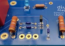
The PCB was laid out the better part of a decade ago when the future availability of J74 transistors was very much in doubt, and a number of things were added to the PCB in case we had to depend on a different transistor type for the front end P-channel differential pair. That’s why there’s so many jumpers and resistor pads that nobody ever uses for resistors, an just install jumpers.
So, now that we know why, here’s the list of thing that should be considered “normal”
J1
J2
R6
R30
and R27a (the R27 between the capacitors)...
...should all be jumpers.
Use wire, use cut-off leads from resistors if you like, or for awesome style points, get zero ohm resistors. 🙂 (Yes, there is such a thing...)
R8 is a pad for a trimmer potentiometer, but like all the pot pads on the board, there’s a place for a fixed resistor across it. R8 should be a 1K resistor, not a pot.
For clarification on the schematic, R27b is the place for the fixed resistor across the R27 pot, but that position needs to be a potentiometer, and you should pre-set it to about 68K before you solder it.
And lastly, just to make sure everybody is on the same page, this is the schematic that matches the PCB -
I really, really appreciate 6L6's work and passion over the years to populate and advance this hobby. But the simple fact is that he is speaking/typing Greek to me.
If I asked you to reply to me and this comment with a triple, introductory adverbial phrase in the first sentence and a noun clause as the subject of the second sentence, and a right-branched, compound, complex third sentence with active verbs and no subject complements in the predicate, would you even know what I'm talking about--even if you Googled it?
The point of this thread is that I don't know those words that 6L6 used in his build thread, and he brought them over here (with good intentions!) without explanation. They impart no meaning onto me. That goes for a lot of the comments that start on page 3-4 of this thread.
Look, I don't even know what a snubber is. What is a variac? What do you even mean by bulb tester? What even is a diode and a rectifier and a bridge, and how should I know to do it this way versus another way?
A few weeks ago, I bought the AJ amp boards and BOM and chassis and thought I was good. I recently discovered I needed a PSU, and then all these measurements and... JFC... I want to throw in the towel. And while I'm a noob, I've successfully built other DIY hum-free, SET tube monoblocks.
Appreciate ya'll, but you need to put yourself back to 3rd grade to explain these things that are fundamental to you that we haven't learned yet (not fundamental to some of us). That's the point of THIS thread. Really need more definition and less "tell."
This is where *I* am coming from and, presumably, others, too.
Hahahaha
You have to say: "Hey you dumb bastard, what is a bloody variac, do I look like a bloody mind reader"
That usually works for me.
You have to say: "Hey you dumb bastard, what is a bloody variac, do I look like a bloody mind reader"
That usually works for me.
Feel free to ask a million questions.
We are a very lazy bunch of people, when it comes to writing more than a paragraph.
No more than 2 questions at a time is preferable.
We are a very lazy bunch of people, when it comes to writing more than a paragraph.
No more than 2 questions at a time is preferable.
I'm starting to dry fit things, I bought 10mm standoffs, and now I'm worried I don't have enough of the leads from the power transistors coming through the boards. Am I okay, or do I need to order 5mm standoffs? There's enough there to make the connection but....
Attachments
1. That's fine, just solder the leads properly
2. The leads do not have to bend at 90deg; you could try to feed more of the legs through the eyelets if you bend the leads with some radius.
3. IMPORTANT: tighten the transistors firs, BEFORE you solder them.
2. The leads do not have to bend at 90deg; you could try to feed more of the legs through the eyelets if you bend the leads with some radius.
3. IMPORTANT: tighten the transistors firs, BEFORE you solder them.
Looking forward to the power supply section
I've been checking in frequently and keeping up with this very helpful thread. I'm at the challenging transition from building full kits (two ACAs and a Bottlehead Crack w/speedball), and wow, this sure looks more difficult, especially building the power supply. The build guide for the DIY ups seems to have metastasized! Its now over 130 pages and 1,300+ posts, so I'm finding that daunting.
So, thanks to all involved for starting and carrying this forward. I've bought the Aleph PCBs and transistor sets, and had thought I'd get the power supply built first, but after a few hours of grinding through the build guide and (much shorter?) discussion thread, its clear I'm over my head without some more focused and concise instructions. And I'm guessing I'm not alone here.
Thanks again.
VineSerf no your not alone here, if the power supply for first watt clones was a sorted kit instead of an a pcb canvas for aspiring electrical engineers I would have had 3 amps built already...I mentioned this at the beginning of the noob thread....it’s like the secret sauce and no one likes sharing there recipes. The noob answers are pretty light as well, I have asked:
About shunts, I know the concept but don’t really understand why I want/need one? Do firstwatt amplifiers come with a shunt? If I do need one why isn’t it included on the UPS PCB?
Bridge or diodes? Diodes seem to be a pita so why would anyone use them when there’s a simple alt?
Grounding? A thousand pitfalls here and the UPS PCB seems to address them in a very rudimentary way.
Many of the firstwatt amps are ‘current limited’ but I get the feeling that increasing the ps sized does not change the limitations is that correct?
Last edited:
- Home
- Amplifiers
- Pass Labs
- Aleph J build guide for noobs