You can buy just the heatsinks for the 4U from our store at a competitive price. As far as dim bulb or variac, I have and use both. With a variac you increase the voltage and look for smoke whereas a dim bulb tester will tell you if there is a problem before smoke, at least most of the time being that some of our NP clones are biased so high the bulb will shine when everything is fine. Then is the time to use the variac.
OK, I've posted our next two blog installments:
Introduction: Tools You Will Need
Parts: Stuff to Get From the DIYAudioStore
As we've still not built our amps, I'm sure these will get revised. Comments and suggestions welcome!
Next task is figuring out how to best organize the list of parts we'll need from Mouser/DigiKey, since the official BOMs are really only the beginning...
Looking good, guys! One thing I noticed in the "Parts to get from the DIY Audio Store" post, and I may be wrong about this as I'm also still just in the planning stages, but I believe you need a total of 4 of the LSJ74 transistors for a stereo amp; 2 per channel. Someone please correct me if I am wrong there but that appears to be the case from the schematics and BOMs I'm looking at.
I only use Variac. My focus isn't on smoke, it's on measurements. If voltage is not acting right as you dial up, shut down before smoke. Same with bias. As voltage rises, bias goes up, you can hold at that voltage, turn back bias, reset off set and continue turning up.
When it comes time to use Semisouths and V-fets, I will drag it out. I'm comfortable enough normally to just use Variac, but the cost of silly mistake killing devices I can't replace, all precaution.
With Variac, I've only cooked 2 front end board mosfets, from crossing a couple power supply wires.
It was my 3rd BA3 Build, was late at night when I wired board to power supply, (tested separately) and just banged it, no Variac.
Bottom line for beginner (or whoever) dim bulb good idea. Very forgiving. Plus, it is WAY cheaper as well.
Russellc
Looking good, guys! One thing I noticed in the "Parts to get from the DIY Audio Store" post, and I may be wrong about this as I'm also still just in the planning stages, but I believe you need a total of 4 of the LSJ74 transistors for a stereo amp; 2 per channel. Someone please correct me if I am wrong there but that appears to be the case from the schematics and BOMs I'm looking at.
Yes you need 4, preferably tightly matched.
I think the store offers them matched.
Yes you need 4, preferably tightly matched.
I think the store offers them matched.
Ha! Good catch, I didn't realize that. Time for a follow-up order, which also gives me an excuse to get the Fire Metall solder.
So is it important to have a matched quad, or would two matched pairs be fine (since I already have one matched pair)?
Good stuff, I am stubborn and am dead set on building my own chassis, Can someone point me to heatsink sizing info? Also some PS questions, I feel like mono bridges are easier or more straightforward or maybe produce less heat?...is there a reason not to use them? Snubbers, I know the what can someone talk about why and how and are they needed/wanted/nice-to-have. If someone were considering dual mono using the diyaudio store pcb would there be any difference in joining/strapping the grounds on board or jointing everything with a star ground?
Current plan is to use monolithic bridges, per the factory First Watt Aleph J. So far, my inclination is to follow @6L6's advice and go with the GBPC3502, no snubbers needed. For a discussion of pros/cons of monolithic vs. discrete diode bridges and snubbers, I'll recommend the main Aleph J thread. For purposes of the noob guide, I think the reduced parts count and complexity seals the deal.
Ha! Good catch, I didn't realize that. Time for a follow-up order, which also gives me an excuse to get the Fire Metall solder.
So is it important to have a matched quad, or would two matched pairs be fine (since I already have one matched pair)?
You don't need a matched quad, you just need matched pairs.
If the matched pairs are different then just be sure you keep the pairs together and don't mix them up.
If they offer a matched quad you could get that too depending on the price difference.
OK, I've posted our next two blog installments:
Introduction: Tools You Will Need
Parts: Stuff to Get From the DIYAudioStore
As we've still not built our amps, I'm sure these will get revised. Comments and suggestions welcome!
Next task is figuring out how to best organize the list of parts we'll need from Mouser/DigiKey, since the official BOMs are really only the beginning...
I'd suggest using octopart for consolidating your BoM. It provides a quick way to compare part price and availability.
This might help get you started (double check the details, I may have got something out of whack):
web - Octopart
Rod Elliott offers some guidance:Good stuff, I am stubborn and am dead set on building my own chassis, Can someone point me to heatsink sizing info? Also some PS questions, I feel like mono bridges are easier or more straightforward or maybe produce less heat?...is there a reason not to use them? Snubbers, I know the what can someone talk about why and how and are they needed/wanted/nice-to-have. If someone were considering dual mono using the diyaudio store pcb would there be any difference in joining/strapping the grounds on board or jointing everything with a star ground?
DIY Heatsink
Check the link in the article to the calculator.
Another port of call is Conrad Heatsinks - Technical Details
There's sure to be other good stuff on the forum here but the above should get you some ways down the path.
Lastly, don't forget the info provide by the store - 40mm Heatsink Information – diyAudio Store
Last edited:
Next task is figuring out how to best organize the list of parts we'll need from Mouser/DigiKey, since the official BOMs are really only the beginning...
Correct.
Also understand that a populated one click cart will require almost constant maintenance and updating as parts go in and out of stock, and part numbers change. Or give the carts about 6 alternate part numbers (yes, really) per part to help insure that the one-click works over time.
The real trick is to make a BOM that has notes or specifications about Resistor wattage, capacitor voltage, what fits the PCB, lead spacing and footprints or diameters, etc... that kind of information.
Henryve’s BOM here has some good notes at the bottom, well worth integrating into what you are making. 🙂
https://www.diyaudio.com/forums/att...eph-universal-mounting-spec-bom-aleph-ums-pdf
Also, since we are talking BOM may I clarify a few things...
The PCB was laid out the better part of a decade ago when the future availability of J74 transistors was very much in doubt, and a number of things were added to the PCB in case we had to depend on a different transistor type for the front end P-channel differential pair. That’s why there’s so many jumpers and resistor pads that nobody ever uses for resistors, an just install jumpers.
So, now that we know why, here’s the list of thing that should be considered “normal”
J1
J2
R6
R30
and R27a (the R27 between the capacitors)...
...should all be jumpers.
Use wire, use cut-off leads from resistors if you like, or for awesome style points, get zero ohm resistors. 🙂 (Yes, there is such a thing...)
R8 is a pad for a trimmer potentiometer, but like all the pot pads on the board, there’s a place for a fixed resistor across it. R8 should be a 1K resistor, not a pot.
For clarification on the schematic, R27b is the place for the fixed resistor across the R27 pot, but that position needs to be a potentiometer, and you should pre-set it to about 68K before you solder it.
And lastly, just to make sure everybody is on the same page, this is the schematic that matches the PCB -
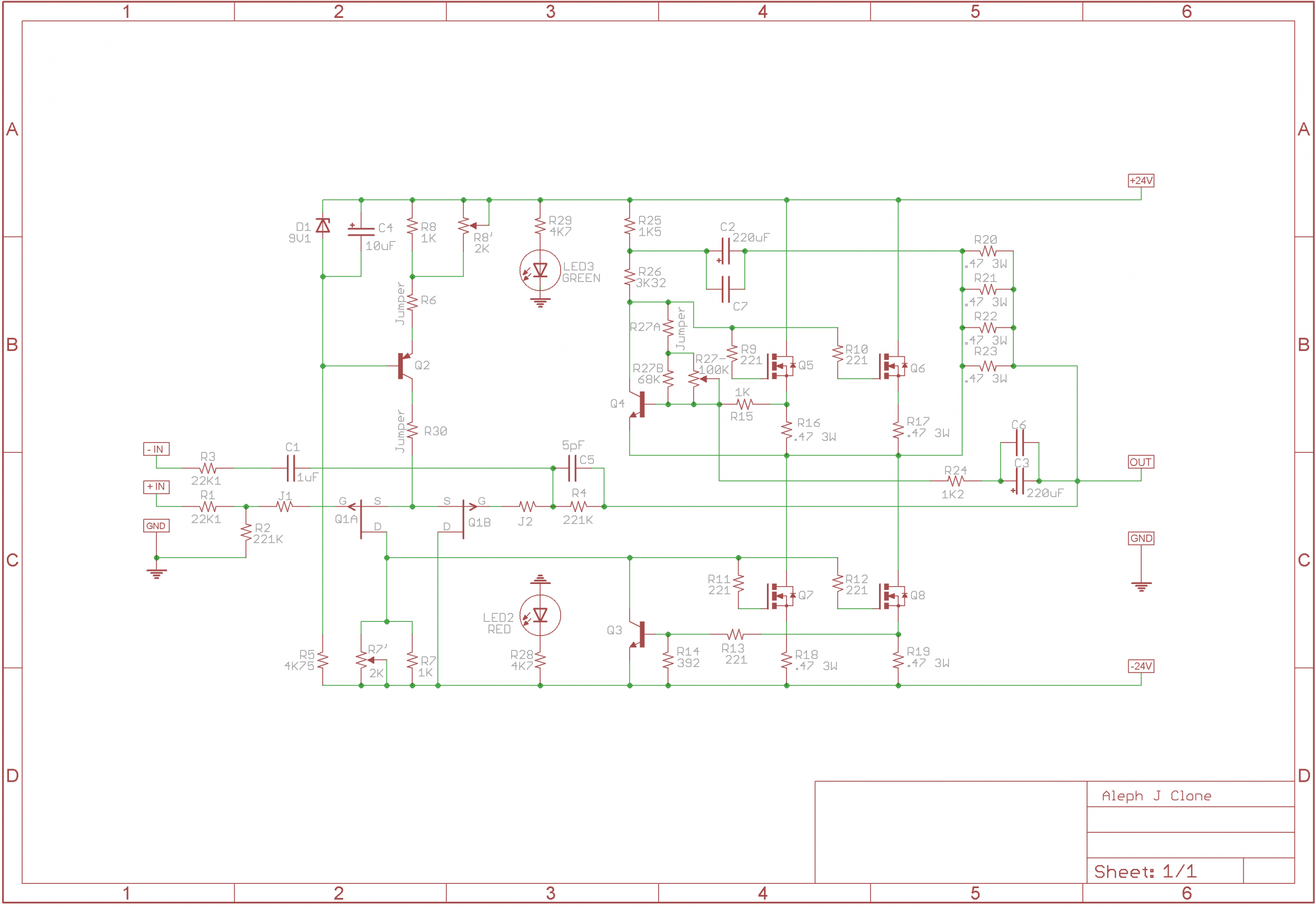
Last edited:

They seem really nice. A lot of capacitance in 35mm X 52mm package.
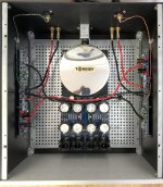
Make sure you go big in chassis size with 2 X 400VA transformers.
Try to position the transformers and the PS PCB in such a way to minimise the AC wiring length, as well as DC hook-up wiring length.
Make sure you go big in chassis size with 2 X 400VA transformers.
Try to position the transformers and the PS PCB in such a way to minimise the AC wiring length, as well as DC hook-up wiring length.
Attachments
I was thinking along these lines for power supply caps, Nichicon 15,000 uf, 30mm, 105C, 35V. This would be for our more plain vanilla build with a single transformer, rather than dual mono, good for transformers with either 18v or 20v secondaries.
Any thoughts on pro/con on going for 30mm vs. 35mm caps (crowded on the board, harder to solder?), and whether extra capacitance (27k vs. 15k) would really make a difference (First Watt used 15k uf caps, no?)?
Any thoughts on pro/con on going for 30mm vs. 35mm caps (crowded on the board, harder to solder?), and whether extra capacitance (27k vs. 15k) would really make a difference (First Watt used 15k uf caps, no?)?
As between 30/35 I don’t think there’s a difference in available room or soldering. Will more cap make a difference? I don’t know. From what I’ve read it might so...cost isn’t huge to use more and I’ve not heard of any downside. I’m sure there’s a point of diminishing returns and as you said the stock 15k is probably perfectly fine. Of course stock is built to a price point and so as a DIY you *might* have an opportunity to improve.
Generally speaking, rated ripple is directionally proportional to the can size.
27K vs 15K is almost twice the capacitance, there will be a noise difference that's measurable. Wether or not that makes an audible difference is debatable.
27K vs 15K is almost twice the capacitance, there will be a noise difference that's measurable. Wether or not that makes an audible difference is debatable.
27K vs 15K is almost twice the capacitance, there will be a noise difference that's measurable. Wether or not that makes an audible difference is debatable.
@6L6, sorry for being a dense noob about this, but can you say a little more about this? I understand the basic principle of filter caps for reducing ripple, but not the relationship between noise and capacitance. Does more capacitance result in higher or lower noise? Why? (I promise, I spent 15 minutes Googling for the answer before giving up and asking here.)
- Home
- Amplifiers
- Pass Labs
- Aleph J build guide for noobs