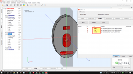
Not sure how many users of AKABAK3 keep on top of the updates, but the latest version has added a simple mesh validity check at solving time. Invalid or overlapping mesh elements will be highlighted in pink if the relevant checkbox is selected on the right-hand panel.
The help file has also been updated accordingly, with suggestions.
This is something I asked for last summer via email and can be very useful when working with more complex geometry.
The help file has also been updated accordingly, with suggestions.
This is something I asked for last summer via email and can be very useful when working with more complex geometry.
Thanks for the tip Kyle. I have been working on generating horn mesh files in Octave as text .stl files that I then run through gmesh to export as a version 2 ascii .msh file to use in AKABAK. As these are already mesh files gmesh can't remesh them (AFIK) and I define the triangles manually, this means I have precise control of how the mesh is generated. Initially I generated the mesh to just physically represent the object (IE for a plane just two triangles), however my simulations where not at all acurate and showed numerical instability. Setting the minimum edge length parameter in AKABAK however seems to clear this up but very quickly results in too many elements. I reason that if I make my mesh more fine (IE maximum triangle size) I won't have to set this parameter and will still get good simulation results. Is there any other parameter I should use to refine the mesh? (EG I have seen curvature used in GMESH).
Last edited:
I'd be careful defining the mesh manually. To get anywhere near the resolution of tetrahedra you need, in 3D, takes some serious maths. If anything, AKABAK3's built-in frequency-based meshing is on the loose side, as it only uses half the wavelength of the highest frequency as a guideline. The generally accepted element size is one-sixth of the wavelength, although you can get away with fewer on some larger domains. The real issues occur in horns when the boundaries become close, as the elements here must be small enough that their 'extended halo' doesn't overlap with the surface opposite.
There's a good example of that in the updated manual; this is also an example where the element size by curvature can be useful in Gmsh, but not all narrow channels are curved. For that reason, I tend to manually slice up my geometry into sections, and mesh each of them manually according to guidelines and a touch of intuition. That also has the benefit of being able to just reload that section's mesh for a different one in AKABAK3, if a higher resolution or geometry correction is necessary.
For example, I recently made a model of a large Paraflex sub which used 111 frequencies from 10 to 250 Hz. To get accurate results, the narrow channels near the driver needed to be defined as separate subdomains, with a much finer mesh than the larger rear chamber and final segments near the mouth. I'm talking 30 mm element sizes to avoid issues with the 'other side' of an 18 mm panel preventing the model from solving, and to account for a large amount of resonance in these areas.
As an aside, the story of tetrahedral algorithms is actually pretty interesting and wasn't a problem that could be solved until quite recently (in mathematics terms).
https://www.quantamagazine.org/triangles-are-easy-tetrahedra-are-hard-20220131/
I don’t want to make assumptions about your maths skills, but it’s not something I’d be attempting to do manually myself!
Are you using Octave to determine geometry based on equations? If so, it might be better to take the approach of something like Ath, and define the derived geometry using simple shapes and curves. Ideally, you want the elements as fully parametric nodes and splines, or nodes and vertices, exported into STEP format rather than an existing mesh to allow the most flexibility working with Gmsh.
There are also ways to generate geometry in CAD tools using equations, or to link them with Octave/Matlab. I'm pretty sure you'll find something like that for FreeCAD, or there's also Rhino with Grasshopper.
I'm making a 2" throat horn for the 400-4000 Hz range, 90x60 with 'good' loading, something like the CE horns described here for the M200 or a BMS/AXI2050 midrange comp. So I need to have discontinuities in the horn in order to change defining equation at certian points. So far my first attempt got the loading right and exhibited constant directivity but only 60 degree horizontal dispersion, I might need to incorperate a diffraction slot to meet my objectives (I can't just go to a giant conic like horn like the K402 as the system already has one massive horn and we will run out of van space if I keep it up). I also have throat adapters I have designed for the round to square transition which are not equation defined So I don't see the ATH4 working for me. I would idealy export 3D models rather than STL though but the formats looked quite complicated on first inspection.
Seems dumb but I hadn't realized that AKABAK3 was using tetrahedra which means that it must be building off the existing geometry I give it in some way as thats just triangles. I find if my simulation has much over 8000 elements it just gets stuck at 16%. "The real issues occur in horns when the boundaries become close, as the elements here must be small enough that their 'extended halo' doesn't overlap with the surface opposite." this is a very useful tip and I think if I try and ensure that I'm getting multiple triangles across the horn surface this should improve the quality of the results. Will check the AKABAK manual in the latest version...
Seems dumb but I hadn't realized that AKABAK3 was using tetrahedra which means that it must be building off the existing geometry I give it in some way as thats just triangles. I find if my simulation has much over 8000 elements it just gets stuck at 16%. "The real issues occur in horns when the boundaries become close, as the elements here must be small enough that their 'extended halo' doesn't overlap with the surface opposite." this is a very useful tip and I think if I try and ensure that I'm getting multiple triangles across the horn surface this should improve the quality of the results. Will check the AKABAK manual in the latest version...
That makes sense, but I still think you might have better luck using parametric CAD geometry concepts to join simple shapes together. Acoustically, a stepped series of conical or cylindrical shapes represent most horn geometry, so it might just be a case of sensibly dividing the final horn geometry into fine enough segments?
You can also 'draw' and join surface shapes using Gmsh itself, either in the GUI or via the CLI. I've not tried anything complex, but I did find it a little easier than defining the geometry directly in AKABAK3 for anything that isn't a simple set of flat, planar rectangles.
That might also be where you're getting confused about how the mesh is defined. You do only end up with triangles, since the BEM only solves the integral across the defined surfaces, and not for the volume between or around those. That's also true for videogames and the like, the stuff you see is 'just triangles' - but the tricky maths is defining where those patched triangular surfaces go to sufficiently portray a complex three-dimensional shape.
Think of it like this; unless your horn is using purely flat planes or conic sections, then the mesh generation algorithm has to consider curvature and deformation in 3D. That also may be a reason why models exported from SketchUp are often a memory-heavy mess of thin, oddly oriented slices - exactly the sort of thing the BEM solver hates.
Considering the wealth of tools for creating parametric surfaces in 3D, many of them free, at least you have options!
As for the solver stalling, this might be a memory issue. Try breaking the model into more subdomains, which appears to help with the distribution of the matrix calculations across your CPU's threads - each of which need to have 4 GB of RAM available (quoting from memory (sorry) 🙂 ) alongside enough memory to store the general model without writing to your disk's swap file, or generating errors which require a recalculation of that matrix index...
That means you might find faster, more stable results setting the AKABAK3 preferences to use fewer threads if you're 'short' on RAM. I've got 12 threads available on my desktop, and I had to upgrade to 48 GB of RAM mid-way through my dissertation to prevent the BEM solver step stalling on complicated models with ~9000 elements or more.
Eventually, I got fed up and re-drew the entire cabinet geometry from scratch in CAD, sliced it up in a different way, and ensured 'best practice' for mesh element length based on the distances involved. These models were of 8 LABhorn, and there's no copy/paste for subdomains or groups in AKABAK3, so you can imagine this was a chore.
The new single horn model solved in 11 minutes, compared to the previous one's 2 hours. For the clustered array models, results were in VACS in hours rather than days 😆 I opened the original model in the new version of AKABAK3 last week, and sure enough, there were some pink bits identified by this new mesh checking process. Only a tiny few, but they count!
This is how I currently generate the surface of the horn, rectangles divided into two triangles. I have 32GB of ram and can have upto 8 threads. Visualy everything looks very smooth. I do have the considerable optimisation available of simulating a quartered horn which will get me to 4kHz just brute forcing the thing with the global edge length parameter. Anyway will have a play around to see if I can get this working better!


n BEM there is in principal a small exclusion zone around each boundary element within which the sound-field becomes undefined. In theory this zone is infinitesimal small but because we deal with finite elements the size of this zone is finite as well. Normally the auto-mesher makes the elements small enough so that in turn the mutual distance is large enough compared to the wave-length. However, elements can also be too close when, for example, a narrow duct is modeled. Elements of opposite walls may then violate this criterion. Another case is elongated triangles where the distance of the center points is much smaller then the length of the sides. In general, picture a small halo over each triangle having a radius of the inscribed circle. In a good model there is no intersection of these hemi-spheres. Narrow ducts need to be modeled with a higher resolution.
Confirmation in the manual that elongated triangles like I generated are bad for the AKABAK meshing algorithm. I have almost completed my changes that allow adjustment of the mesh resolution across the horn and producing quartered horns so should be getting higher frequency results faster soon!
Also another question: I'm currently using a square source to drive the horn as I will design the horn and then do a further simulation with the throat adaptor portion that does the round to square transition. Is this approach valid?
That’s good to hear, as I had made a mental note to pop back and mention the thin triangles problem earlier today when I saw your render 🙂
A square source will have different directivity to a circular piston, but at these sorts of sizes, it’s likely to only affect the upper response of the horn anyway. It might be worth trying a short, simple transition from a circle to the square throat using a loft function in FreeCAD or something on an example horn, so you've got a visual comparison of the sort of impact.
A square source will have different directivity to a circular piston, but at these sorts of sizes, it’s likely to only affect the upper response of the horn anyway. It might be worth trying a short, simple transition from a circle to the square throat using a loft function in FreeCAD or something on an example horn, so you've got a visual comparison of the sort of impact.
I'm just starting to learn AKABAK. I have not yet fully read this thread so sorry if it's already answered - There is a 'Tutorial' folder inside the examples folder with some project files. Where is the tutorial text to go with it?
There is no tutorial text, only one video about making simulation project SP38 what is also in Tutorials folder: http://www.randteam.de/_Videos/Akabak-SP38-MeshFile/SP38MeshFile.html
Thanks, I had missed that!There is no tutorial text, only one video about making simulation project SP38 what is also in Tutorials folder: http://www.randteam.de/_Videos/Akabak-SP38-MeshFile/SP38MeshFile.html
I want to learn Akabak so I can investigate a waveguide I made. It is good on-axis but has a 5KHz bump off-axis.
To help me sharpen my new Akabak skills I wonder if there are some 3D model files for tweeter waveguides out there? Then I could 3D print a real life one and compare to the Akabak model.
I did see a this thread, but the links are dead 🙁 https://techtalk.parts-express.com/...7600-3d-printed-waveguides/page36#post1398387
You can generate all sorts of waveguides using the Ath4 software by mabat, which is shared on this same forum. It generates coordinates for ABEC3, but these can be imported into AKABAK3.
If you download the older ABEC3, linked from the Ath4 site, it also includes many of the same examples with more explanatory text included.
If you download the older ABEC3, linked from the Ath4 site, it also includes many of the same examples with more explanatory text included.

Thanks that's pretty cool!You can generate all sorts of waveguides using the Ath4 software by mabat, which is shared on this same forum. It generates coordinates for ABEC3, but these can be imported into AKABAK3.
If you download the older ABEC3, linked from the Ath4 site, it also includes many of the same examples with more explanatory text included.
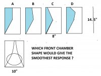
Is there any rule of thumb about what various geometry changes will do acoustically?
For example I used the demo1 config and simply set the length shorter as I desired. I get a pretty steep profile. If I randomly mess with the terms I can get a more gentle profile but I've no idea what any of it will do acoustically until I go to BEM. I guess what I'm asking is what kind of terms should I use to get a nice performing shallow waveguide like the popular Visaton WG148?
I think I'm getting the hang of it. Outputting project files for ABEC / AKABAK is such a time saver!

If you click on the Field element in the 3D view, you’ll see the triangles generated by your current meshing parameters. Those can be modified separately on a per-element basis, and I’d advise that for most models using elements that are not meshed in advance using external tools.Any ideas what is going on here with the diamond shaped hole in my observation plane?
View attachment 1031869
If the elements don’t line up due to different resolutions or the like, there’ll be a ‘hole’ in the mapping. That doesn’t mean there’s nothing happening there, just that the data points span multiple other elements on the main geometry.
You can supposedly define an observation Field by an imported mesh, such as a flat plane in your CAD software that is intersected / ‘punched out’ by the main geometry. That should then follow the surface element profiles more accurately, but it didn’t work for me and I never got around to investigating properly. I think this method also limits the sort of data you can map onto the Field surface too.
- Home
- Design & Build
- Software Tools
- AKABAK 3