So its more comfortable to be the victim of prevailing dogma?
You may need to read the thread title again, Then, again. One more time.
...unless you feel an urge to listen to an audio analyzer.
Consider also the propagation delays within you time plot 😀 😀
Hp
Propagation delays or timings are not an issue for my original target (I2S input or ADC) since in my case ADC is the I2S master and MCK is not even sent to the MCU. For I2S output propagation delays may become an issue with isolators at high speeds (384k and above). This may be the reason why some of the popular usb2i2s boards have reclocking after isolators.
But when it comes to full-duplex I2S these issues get more complicated especially since there is no data available on the STM32 SAI propagation delays. At least in theory the timings in my case should be similar to Pavel's: #1185. The isolators I'm now using have slightly shorter propagation delays (max 10.5ns) but other than that there is not much else to do if I want to keep this uncomplicated and the costs reasonable.
/Martti
hm, about propagation delay, is that really interesting? I remember, I tested that and got 10mS at ASIO4ALL 192k for AB ADC to USB DAC or let's say 5mS per ADC and 5mS for the DAC. For a gaming, or real-time music performance it is fine, what is the reason to improve that?
Propagation delays or timings are not an issue for my original target (I2S input or ADC) since in my case ADC is the I2S master and MCK is not even sent to the MCU. For I2S output propagation delays may become an issue with isolators at high speeds (384k and above). This may be the reason why some of the popular usb2i2s boards have reclocking after isolators.
But when it comes to full-duplex I2S these issues get more complicated especially since there is no data available on the STM32 SAI propagation delays. At least in theory the timings in my case should be similar to Pavel's: #1185. The isolators I'm now using have slightly shorter propagation delays (max 10.5ns) but other than that there is not much else to do if I want to keep this uncomplicated and the costs reasonable.
/Martti
So an opened question...
. may simpler or better to isolate the USB connection as I use INTONA gear
. to support one day DSD / DOP as the ADC have to be the master anyway as AKM AK557X
. have to check about DAC as slave
. one thing about using dual ADC as dual mono, they have to be slave as using dual ak557x otherwise 2 none synchronised bck clocks
. as I see to support, ADC only, DAC only and ADC & DAC
. may 2x channel bundeling to get double speed... it is all about bit clock shifting
. may provide 2 individual USB id's so two of them used on same maschine, as using for none coherent measurements
just my 2 cents 😀
hp
Ok,
new ak4493S as ak4493.in hard coded client mode only.
AK4493SEQ | Audio D/A Converters | PRODUCTS | Asahi Kasei Microdevices (AKM)
new ak4493S as ak4493.in hard coded client mode only.
AK4493SEQ | Audio D/A Converters | PRODUCTS | Asahi Kasei Microdevices (AKM)
It’s a (re)start, but at 113dB SINAD it’s no threat for ESS.
As it goes with Ak4499 ... dam dead 😱
AK4493 as using 3'th order SDM is very very poor 😀
And I am still interested about any PN/jitter figures of AKM and even ESS too 😀
BTW: I would love may ugly UFL connections and for master clock a nice SMA connection with 2 x 100E pullup-down resistors and stay within 30..70% required digital levels.. does this ESS requires too while no NDA
 ??
??And I am still interested about any PN/jitter figures of AKM and even ESS too 😀
What do you mean by that? The jitter impact on the analog performance? Won't happen, it is likely way under any usual analog instrumentation sensitivity. Otherwise, I just got (almost for free) a PN9000 Phase Noise (and Jitter) analyzer and I am looking forward for some real world use case. I'm bored of calibrating and measuring Wenzel, MTI, Morion, Bliley and PNI oscillators phase noise and jitter 😀.
The PN9000 seems to have pretty remarkable performance given its architecture. I will be interested in seeing what you can measure, particularly audio frequency related. It seems to be really focused on radar applications.
Mine does everything, from 2MHz to 26GHz, all known PN measurement methods, PLL OCXOs (10 & 100MHz), Synthesizer (2MHz-1.8GHz base band, up to 26GHz with up/down converters), Delay Line, Addded Noise (with autocorrelation), VCO, etc... Two racks and one computer, 160lbs. of equipment.
I'll post some test measurements later.
I'll post some test measurements later.
What do you mean by that? The jitter impact on the analog performance? Won't happen, it is likely way under any usual analog instrumentation sensitivity. Otherwise, I just got (almost for free) a PN9000 Phase Noise (and Jitter) analyzer and I am looking forward for some real world use case. I'm bored of calibrating and measuring Wenzel, MTI, Morion, Bliley and PNI oscillators phase noise and jitter 😀.
Yes, all about PN measurements and figures... not what happeneds at the audio end 😀
ADC/DAC added PN/jitter happens IMHO about limitations of the internal switching capabilities... Audio Godfathers do not like to blame turtles ... so after time anyone will get sooner or later after the ****.
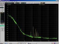
This is my first clock generator measurement. Schematic (there are a few changes)was posted in this thread. Essentially, it's a fractional PLL that generates the audio master clocks for the ADC and DAC starting from a fixed reference of 24 MHz (a 50 cents quartz) which is also used to clock the XMOS CPU. For audio purposes, this is followed by a series of jitter cleaners (also PLLs), based on the Cirrus CS2100 chip.
Attached is the phase noise plot for the worst case of 100MHz output (close enough to the 98.304MHz required for 768K conversion). Reference for the measurement is a Morion MV317 100MHz OCXO. I am sure Andreas will be deeply disappointed on the results 😀.
There are some spurious I cannot identify the source from (they appear always in the same frequency range), also I cannot explain why the noise slope seems to decrease at very low frequencies, but then I am not going to sweat too much over those details.
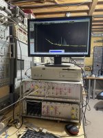
Also attached is a photo of my new toy in action, while measuring some 10MHz oscillator (nothing to call home about) 😀. Now I have to find a good location for it, in an already overcrowded lab...
Attached is the phase noise plot for the worst case of 100MHz output (close enough to the 98.304MHz required for 768K conversion). Reference for the measurement is a Morion MV317 100MHz OCXO. I am sure Andreas will be deeply disappointed on the results 😀.
There are some spurious I cannot identify the source from (they appear always in the same frequency range), also I cannot explain why the noise slope seems to decrease at very low frequencies, but then I am not going to sweat too much over those details.
Also attached is a photo of my new toy in action, while measuring some 10MHz oscillator (nothing to call home about) 😀. Now I have to find a good location for it, in an already overcrowded lab...
Attachments
Last edited:
That's really good for a PLL of any kind. Does the system have some type of self check to make sure what you are seeing is real?
This is my first clock generator measurement. Schematic (there are a few changes)was posted in this thread. Essentially, it's a fractional PLL that generates the audio master clocks for the ADC and DAC starting from a fixed reference of 24 MHz (a 50 cents quartz) which is also used to clock the XMOS CPU. For audio purposes, this is followed by a series of jitter cleaners (also PLLs), based on the Cirrus CS2100 chip.
Attached is the phase noise plot for the worst case of 100MHz output (close enough to the 98.304MHz required for 768K conversion). Reference for the measurement is a Morion MV317 100MHz OCXO. I am sure Andreas will be deeply disappointed on the results 😀.
There are some spurious I cannot identify the source from (they appear always in the same frequency range), also I cannot explain why the noise slope seems to decrease at very low frequencies, but then I am not going to sweat too much over those details.
Also attached is a photo of my new toy in action, while measuring some 10MHz oscillator (nothing to call home about) 😀. Now I have to find a good location for it, in an already overcrowded lab...
Really? and why?
The poor Timepod measures exactly like your PN9000.
Already compared, maybe you have not read carefully
The Well Tempered Master Clock - Building a low phase noise/jitter crystal oscillator
That's really good for a PLL of any kind. Does the system have some type of self check to make sure what you are seeing is real?
Yep.
Really? and why?
Because I knew you will jump from your neck of woods, as defensive and trashy as usual.
This is not for a DAC that you and your posse your Golden Ear Brigade would listen to. So I did not compare the PN9000 with the timepod, and there's anyway nothing for you here.
Last edited:
You are right, we are not particularly interested on listening to your devices.
And I well know there is nothing for us here since you still keep measuring THD.
However, now you have a good phase noise analyzer tool so you could build yourself an upconverter in order to measure in audio band (at DAC output).
And maybe if you share the upconverter design you saved us a lot of time.
You are right, we are not particularly interested on listening to your devices.
And I well know there is nothing for us here since you still keep measuring THD.
Glad we agree, so please STFU and walk.
Wow, now you are the owner of the forum, sorry but I didn't get it.
I forgot, if you mention me, expect me to respond to your comments that concern me personally.
I forgot, if you mention me, expect me to respond to your comments that concern me personally.
Last edited:
- Home
- Design & Build
- Equipment & Tools
- ADCs and DACs for audio instrumentation applications