It's not about I2S vs. left-justified (obviously the conversion would use left-justified), but about max. bitclock supported by my DAI (which runs OK at 36MHz but unreliably at 49MHz).
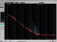
I promised some time ago (can't find the post in one of his threads) to Andreas that I will dig in my archives and post the MTI240 10MHz oscillator phase noise measurement results, using my E5052A. Didn't find them, but since I don't like leaving unhonoured promises, here's the PN9000 result.
A pretty good tunable OCXO, noise floor at -165dBc is excellent, but the noise corner frequency is not that great (a few hundred hertz). Reference was a Morion MV336 OCXO.
A pretty good tunable OCXO, noise floor at -165dBc is excellent, but the noise corner frequency is not that great (a few hundred hertz). Reference was a Morion MV336 OCXO.
Attachments
As for the last feature, "I am not a golden ear"but then who cares about except the non stationary, time variant, noise modulated fear mongers with golden ears?
To call out tin ears, one would first have to have golden ears, no? Otherwise it's like pot calling out kettle about the appearance. 🙄What about the fear mongers with tin ears, but lots of test equipment?
As pointed out earlier, I like to have the master clock generated close to the ADC and DAC if possible.
But if the ADC and DAC needs to be isolated, what will be the best way to deliver an isolated clock?
Digital isolators are of course an easy solution and it seems like some isolators actually perform reasonably well in terms of jitter. But how about using a transformer?
Some time ago I made some experiments using a 10/100 Ethernet transformer to transfer the master clock. These transformers are low cost and intended for the relevant frequency range. It looked promising, but I didnt have the tools to verify the actual performance.
Perhaps you could test that syn08, with your new toy?
That's a great suggestion, I have some old ethernet cards in the junkbox ready to be massacred for parts. It will take some time tough, I have to see how to adapt connectors to it. Sometime next week.
Sounds good 🙂
The next step, after the transformer is of course the "receiver". Balanced receiver, inverter or?
The next step, after the transformer is of course the "receiver". Balanced receiver, inverter or?
The Ethernet transformers are well suited and they have additional common and normal mode isolation. Here is some info: https://www.haloelectronics.com/pdf/discrete-ultra-100baset.pdf And due to volume they are pretty cheap. After reviewing the drawing it really leaves me puzzled by some of the Ethernet isolator nonsense being sold to audiophiles. Well, a fool and his money are soon parted*
I have used transformers very successfully for clock distribution. You get good isolation and it should be pretty free of much added phase noise and no power supply issues. Figuring the optimum drive and best receive strategy will be the next task.
*Dr. John Bridges' Defence of the Government of the Church of England, 1587
What I used in that application was to injection lock a local oscillator (2 gates and a crystal) which worked well. At least you can be sure the circuit is working even if the master clock is not. However not that practical here.
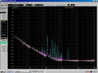
This is my first clock generator measurement. Schematic (there are a few changes)was posted in this thread. Essentially, it's a fractional PLL that generates the audio master clocks for the ADC and DAC starting from a fixed reference of 24 MHz (a 50 cents quartz) which is also used to clock the XMOS CPU. For audio purposes, this is followed by a series of jitter cleaners (also PLLs), based on the Cirrus CS2100 chip.
Attached is the phase noise plot for the worst case of 100MHz output (close enough to the 98.304MHz required for 768K conversion). Reference for the measurement is a Morion MV317 100MHz OCXO. I am sure Andreas will be deeply disappointed on the results 😀.
There are some spurious I cannot identify the source from (they appear always in the same frequency range), also I cannot explain why the noise slope seems to decrease at very low frequencies, but then I am not going to sweat too much over those details. ...
"Before I respond just give me a moment to bask in the radiance of your wisdom"
(Thanks, Jan!)
You should rush your result to Noise XT (successor to Aeroflex)
The might not have realized how good their grandpa instrument was. The
development of their new generation device with cross correlation was not only
a bad investment, it was a major step back.
And all that at your first try with the instrument. Don't forget to tell them.
Mindblowing what might result if you learn the finer tricks.
In the meantime, you should read "Rohde, Poddar, Apte: How low can they go?"
< How Low Can They Go?: Oscillator Phase Noise Model, Theoretical, Experimental Validation, and Phase Noise Measurements | Poddar, Ajay K.; Rohde, Ulrich L.; Apte, Anisha M. | download >
And Cirrus will be most delighted to hear that their jitter cleaner works so
nicely at 100 MHz, and not only from 6 to 75 MHz as their surely faulty data
sheet suggests.
All that from a 50 ct. computer xtal. Wenzel, Synergy, Morion etc will be kicked away!
OTOH you might go sweat over this or that detail or ask yourself why you got
the device for next to nothing.
Gerhard.
I don't see anything that goes beyond what the data sheets are telling about these oscillators and yes, the CS2100 works just fine at 100MHz and, when cascaded, do wonders in cleaning the phase noise floor (not so good in the close in phase noise).
Thanks for taking the time to go through all those data sheets, specifications, etc... I would apologize for daring to post something that yet again stepped on your ego.
Thanks for taking the time to go through all those data sheets, specifications, etc... I would apologize for daring to post something that yet again stepped on your ego.

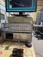
Jen, it was easier than expected, found an old 10/100MB card right away. The transformer is 16PT8515, data sheet is attached. I measured the MTI240 phase noise directly and through the transformer. Net result, no difference, everything is within the instrument measurement error of +/-2dB.
A pulse transformer looks like a very good solution. One caveat though, not sure how it will behave with square wave, the phase noise energy is then distributed across harmonics. I would not expect much trouble though, these small transformers have good bandwidth (the one tested is spec'd
at 80 MHz).
Attachments
I suspect you have a VNA in that wall of expensive instruments. You could sweep it to see its bandwidth and any other relevant issues.
Transformers do make a lot of sense for distributing clock signals. Less so for data if the imbedded clock is critical.
Transformers do make a lot of sense for distributing clock signals. Less so for data if the imbedded clock is critical.
syn08, that was quick! 🙂
Then we just need to make sure the driver and receiver don't add significant jitter.
Then we just need to make sure the driver and receiver don't add significant jitter.
Interesting, I tried the CDCE chips when I was dealing with the ADC (got a demo board from TI), and didn't cut it for me, the jitter was poor. That was over 6 months ago, perhaps I did something wrong.
Well it depends which ones you used TI have many different devices that start with CDCE. As far as I can tell it's a bit like saying I tried the OPA chips and they were too noisy.
The CDCE18005 is just a clock distribution buffer. It takes my two NDK oscillators as inputs and then pipes them to whichever output you want. Formats them into a variety of output standards and adds clock division if wanted. It apparently adds in 200fs of random jitter.
I don't see anything that goes beyond what the data sheets are telling about these oscillators and yes, the CS2100 works just fine at 100MHz and, when cascaded, do wonders in cleaning the phase noise floor (not so good in the close in phase noise).
Thanks for taking the time to go through all those data sheets, specifications, etc... I would apologize for daring to post something that yet again stepped on your ego.
There was not much of a search.
BTW the cs2100 replaces the scaled input signal with an on-chip LC VCO
that is only slowly guided by the input frequency. The input signal may
even miss for some time. Close-in phase noise is not expected to be
good because of the limited Q of the on-chip LC VCO. The data sheet
is vague here, which does not come as a surprise.
In the data sheet of a clock cleaner I would expect a PN plot.
Cascading several leaves you with the properties of the last one in the chain.
Attachments

Last edited:
Thanks for the explanation, although it was not asked for, last time I've checked I succeeded reading a datasheet myself. 70pS RMS period jitter out of the CS2100, that's the spec. Unless you are in the Jiteratti team, that's all an audio appliance will ever need. In practice, and after syncing with the reference clock, it appears much better, anyway.
And you obviously didn't understand the experiment. The 50c. crystal was the "to be cleaned by the CS2100" source, the reference was a (divided) 100MHz Morion MV317 oscillator.
"Cascading several leaves you with the properties of the last one in the chain."
Not if you sync the output with the reference clock. A D latch is all it takes.
The radiance of your wisdom missed the target once again.
Last edited:
70pS RMS period jitter out of the CS2100, that's the spec.
Question for the non-jitterati: how are all these various jitter figures supposed to be compared? E.g. the isolator I'm using has peak eye diagram jitter of 90ps and clock jitter rms of 6.5ps (at 500kHz). How does that compare to 70ps RMS period jitter of CS2100 (at 24.576MHz)?
- Home
- Design & Build
- Equipment & Tools
- ADCs and DACs for audio instrumentation applications