It is rather simple. The affected (by jitter) parameter is essentially the SNR. In an ADC, the SNR and jitter are related by SNR=-20LOG(2*PI*Fin*Tjitter). For example, a 20KHz input signal and a 5pS jitter (about what the CS2100 + sync can do) leads to a SNR of -124dB. I am sure some of the jiteratti team members can hear it.
The race for clocks with fS jitter is nothing but BS.
BTW, a good isolator is a perfectly good solution. I was challenged about the isolator jitter impact while developing the ADC described in this thread, and after measuring the SNR of the ADS127L01 I found absolutely no SNR difference (-118dB) with and without isolators. It is true the ADS127L01 is not the quietest ADC around, but then again I would not expect any impact of a good isolator to be measurable up to -125dB SNR. I like a lot Jen's idea with pulse transformers though, will think more about.
Last edited:
It is rather simple. The affected (by jitter) parameter is essentially the SNR. In an ADC, the SNR and jitter are related by SNR=-20LOG(2*PI*Fin*Tjitter). For example, a 20KHz input signal and a 5pS jitter (about what the CS2100 + sync can do) leads to a SNR of -124dB. I am sure some of the jiteratti team members can hear it.
It could be possible.
We need a miracle.
I didn't believe in miracles until someone has measured -150dBc at 10 Hz from the carrier for a 100MHz VCO.
Now I believe in miracles.
Good for you. Miracles are the key of any successful High End Audio business.
Audiophiles cables, femtosecond jitter clocks, Shakti pebbles, quantum purifiers, cryogenic wiring, carbon nanotube resistors, beeswax fuses, Dark Matter Optical Treatment for CD Players, Teleportation Tweaks, to name only a few, are at the core of this business today.
Audiophiles cables, femtosecond jitter clocks, Shakti pebbles, quantum purifiers, cryogenic wiring, carbon nanotube resistors, beeswax fuses, Dark Matter Optical Treatment for CD Players, Teleportation Tweaks, to name only a few, are at the core of this business today.
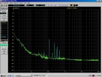
This is my first clock generator measurement. Schematic (there are a few changes)was posted in this thread. Essentially, it's a fractional PLL that generates the audio master clocks for the ADC and DAC starting from a fixed reference of 24 MHz (a 50 cents quartz) which is also used to clock the XMOS CPU. For audio purposes, this is followed by a series of jitter cleaners (also PLLs), based on the Cirrus CS2100 chip.
Attached is the phase noise plot for the worst case of 100MHz output (close enough to the 98.304MHz required for 768K conversion). Reference for the measurement is a Morion MV317 100MHz OCXO. I am sure Andreas will be deeply disappointed on the results 😀.
Because I see people around really like to push my buttons I thought I should revisit these measurements; and indeed I made an "small" error in reporting. The results are NOT for 100MHz as originally stated, but for 10MHz, using the PN9000 OCXO as a reference, upgraded with a Wenzel Streamline OCXO https://wenzel.com/wp-content/parts/501-31686.pdf unit. The conclusions remain the same, my clock generator has very good noise floor, but rather poor close in phase noise, so Andreas business in nowhere in danger
 .
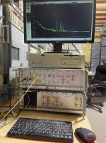
.Sorry for the error, I did too many thinks over the weekend and didn't properly keep track of everything. The error would be obvious for those inquiry minds that would carefully look at the setup photo, rather than scratching their nose while commenting. It is obvious the 10MHz OCXO was in use. I'll post the 100MHz results with the Morion MV317 reference OCXO later tonight.
P.S. A simple inspection revealed the source of those spurious in the 100-1KHz range. They occur at mains frequency multiples, so it's a matter of shielding in my over mains polluted environment. Already discussed this in the LNA threads, I had to shield my best x1000 LNA (yes, massive paralleled JFET based Gerhard, it's perfectly stable) in half an inch of aluminum to clean the output.
Last edited:
> Because I see people around really like to push my buttons I thought I should
> revisit these measurements; and indeed I made an "small" error in reporting.
> The results are NOT for 100MHz as originally stated, but for 10MHz, using the
> PN9000 OCXO as a reference, upgraded with a Wenzel Streamline OCXO
> https://wenzel.com/wp-content/parts/501-31686.pdf unit. The conclusions
> remain the same, my clock generator has very good noise floor, but
> rather poor close in phase noise, so Andreas business in nowhere in danger .
> Sorry for the error, I did too many thinks over the weekend and didn't
> properly keep track of everything. The error would be obvious for those
> inquiry minds that would carefully look at the setup photo, rather than
> scratching their nose while commenting.
I have built 100 MHz oscillators that go into peer reviewed space systems
and I know what is physically possible and what not.
You now concede a times 10 frequency error and back down to a
completely different setup but claim the conclusions stay the same.
I have pointed out your error, that's all.
It's YOU who tries to do phase noise voodoo in the audio field, not me.
That makes YOU a jitterati member, not me.
I find it boring. Phase noise of 15 GHz frequency synthesizers is much
more entertaining, starting with their crystal references.
The experiment to remove you from the ignore list was a complete
failure after 2 days. Back under your stone!
I'm eaglery waiting for someone to show real measurements of how phase noise of an XO translates into the audio signal. I hear something about an up-converter being needed to show this - cannot comment on if that is the correct approach to measure this, it kind of feels wrong though. Why upconvert???
Anyways - up to then all the jitterati and non-jitterati followers are just guessing. Just my 2ct.
PS: We have to take into account the DA converter technology used here - a NOS DAC will heavily depend on low frequency sample clock jitter specs whereas a OS DAC will have completely different behaviour. As I said - waiting for some of you guys with way more test equipment than I own to show real measurements in the aduio domain...
> I'm eaglery waiting for someone to show real measurements of how phase
> noise of an XO translates into the audio signal.
Look into the app notes of 100 MHz+ ADCs. It is a problem there
and it is taken care of.
> I hear something about an
> up-converter being needed to show this - cannot comment on if that is the
> correct approach to measure this, it kind of feels wrong though.
> Why upconvert???
That just solves the problem that the usual phase noise spectrum analyzers
have a lower frequency limit of 1 to 10 MHz since the spectrum they display
is centered around the carrier frequency, and below 1 MHz the sidebands
are seldom symmetrical because of 1/f etc, so the single sided Leeson plot
may show unexpected features.
If you insist that you want to measure the phase noise of very low frequency
signals, then you may convert 0 to 1 MHz to 10 to 11 MHz and measure
the spectrum there. There is the danger that your 10 MHz oscillator used
for the up-mixing is much worse than your device under test. It is not as
easy as it sounds. (pun intended 🙂
And there is an industry consent that there is no market for such an
instrument since the low frequencies are usually generated by dividing
a higher crystal frequency and that solves the problem as a side effect.
The cost of extending the spectrum analyzer towards 0 Hz is too
high to solve a non-problem for most people.
> Anyways - up to then all the jitterati and non-jitterati followers are just guessing.
> Just my 2ct.
No. That is normal textbook knowledge.
Last edited:
I have built 100 MHz oscillators that go into peer reviewed space systems
and I know what is physically possible and what not.
I find it boring. Phase noise of 15 GHz frequency synthesizers is much
more entertaining, starting with their crystal references.
The experiment to remove you from the ignore list was a complete
failure after 2 days. Back under your stone!
- Nobody claimed you are as ignorant as some of your friends around and nobody debated your qualifications and achievments. Admitting mistakes is a sign of strength, not weakness as you seem to believe, and proved by your position in ultimately stupid JFET LNA stability debate, where you programmatically choose to ignore hundreds of practical implementations, measurement and simulation results.
- Yes, the same conclusion, good noise floor but rather poor close in phase noise. Absolute values were wrong, not the shape of the result. A honest approach would be to look closely and point to a very obvious error. Instead, you always choose to jump to the guns, and get frustrated when responded with arguments (even if not always 100% right).
- If audio is boring, perhaps you should find another forum ready to bow to your knowledge and experience, without challenges and debates. Even so, I could help with the 15GHz phase noise, since the new system measures up to 26GHz, but then of course you would have to give up a drop of your ego. Not gonna happen, I know.
- Thank you. After so many years here, my ignore list is still empty. Very few made it temporary in, you are not one of them, only one is still an active member here. Now that I am ignored, I can feel your satisfaction irradiating through the screen glass.
I'm eaglery waiting for someone to show real measurements of how phase noise of an XO translates into the audio signal. I hear something about an up-converter being needed to show this - cannot comment on if that is the correct approach to measure this, it kind of feels wrong though. Why upconvert???
Anyways - up to then all the jitterati and non-jitterati followers are just guessing. Just my 2ct.
PS: We have to take into account the DA converter technology used here - a NOS DAC will heavily depend on low frequency sample clock jitter specs whereas a OS DAC will have completely different behaviour. As I said - waiting for some of you guys with way more test equipment than I own to show real measurements in the aduio domain...
Don't hold your breath. If we are talking about the SNR impact of jitter, then the formula I posted above holds, and the numerical examples shows than anything in the single digit pS could barely be analyzed in the analog domain, set aside any useless debates about audibility.
As of the much invoked close in phase noise effect, I am not aware of any metric that could be conveniently measured in the analog domain. I think Andreas believes he could measure the effects by upconverting the audio signal, but I doubt an upconverter that would bring the audio signals to the RF domain could be build without additive phase noise that would completely obscure the audio signal jitter. I might be wrong, though, and as of the audibility of such effects, I'd rather stop before ruffling more audiophile feathers.
Last edited:
Couldn't you use a time interval analyzer and Allen deviation to get a real picture of both audio clocks and audio output?
I do seriously question the close in stuff, especially after seeing the measured results of a $250K turntable. It's speed stability is in the .1% range and a digital system is in .00001% range or better. If the close in phase noise is important then no analog system would be tolerable.
I do seriously question the close in stuff, especially after seeing the measured results of a $250K turntable. It's speed stability is in the .1% range and a digital system is in .00001% range or better. If the close in phase noise is important then no analog system would be tolerable.
I think that a Stanford SR620 + Timelab software should do *DEV thing.
Maybe I should try that, just for fun.
Oh, think of the horror a LP would produce if the center hole is not
in the center but 0.1mm off. That would result in frequency shift of
the whole music spectrum, about once a second, up and down.
Maybe I should try that, just for fun.
Oh, think of the horror a LP would produce if the center hole is not
in the center but 0.1mm off. That would result in frequency shift of
the whole music spectrum, about once a second, up and down.
My mistake- $500K turntable. Here are some measurements- TechDAS Air Force Zero turntable | Stereophile.com The once around modulation would make getting good close in data nearly impossible I suspect.
I was going to try measuring with my HP5370 but I have not fired it up for some time and there would be a learning curve. However it can measure long periods very accurately.
I was going to try measuring with my HP5370 but I have not fired it up for some time and there would be a learning curve. However it can measure long periods very accurately.
Seeing that TT, the word "Cargo Cult" pops up, as coined by Feynman.
My 5370 is an array of maybe-contacts but I cannot complain. I inherited
it from a fellow ham in the hood. Nobody wanted it because it "only
does 100 MHz". There was a nice 10811A crystal oscillator inside.
Maybe I should clean it up, but there is not much pressure since
I bought the Stanford with valid calibration. I do have even some
spare parts, for example the start/stop oscillator board.
Cheers, Gerhard
I think Andreas believes he could measure the effects by upconverting the audio signal, but I doubt an upconverter that would bring the audio signals to the RF domain could be build without additive phase noise that would completely obscure the audio signal jitter. I might be wrong, though, and as of the audibility of such effects, I'd rather stop before ruffling more audiophile feathers.
And why?
So down conversion works without additive phase noise (for example in your PN9000) and upconversion will not work?
>
Phase noise of 15 GHz frequency synthesizers is much
more entertaining, starting with their crystal references.
Would that include clock generators like Si5340 with VCO around 14GHz? Thanks.
I have no idea about the performance of the Si5340.
I need 9.75 GHz for paid work making some nuclear spin resonance
and I can recycle it for ham radio.
Previously I had a AD synthesizer which had as much output on 5 GHz
as on the wanted 10 GHz. This is a royal pain to remove if you want
to tune it. The TI LMX2594 has 8 VCOs, like organ pipes, and does
7.5 to 15 GHz with the fundamental. Much cleaner.
The onchip VCOs have a resonator Q that is probably much worse
than an xtal, but multiplying 100 MHz by 100 incurs also a 40 dB penalty,
so some of the glory is lost.
OTOH dividing down the 14 GHz to a few MHz as in the Si chips pushes
phase noise down, so the result may be presentable. The main advantage
is that you can program the divider and generate many frequencies from
the same silicon and playing SigmaDelta tricks you may generate odd
frequencies from a given reference.
Like you I got my HP5370 very cheap. It had a dead input but I found a Maxim chip that worked very well and upgraded both inputs to match. I also got the BB Black processor upgrade which also gives it an Ethernet port. However not much need to look at timing issues in the last few years.
Everything I got over the last 20 years was almost dead stuff recovered from trash cans (usually from recycling companies). I recall my 40GHz Wiltron 360B VNAs labeled "Air Force" where I had to start restoring by pulling the floppy disk out of the unit using a pair of pliers. In a 20GHz synthesizer I replaced about 200 tantalum capacitors that were making popcorn sounds when powering up the unit. Etc... but nothing that a good dose of TLC couldn't solve. I have a few certified references (not exactly current, but good enough for me) and a GPSDO for frequency that I use to cross calibrate periodically the gear. Not exactly kosher, and certainly not NIST approved, but works just fine for my needs.
I've no idea what exactly was wrong in my handmade samples I sent Archimago and others but the first 20pcs of SMT production PCBA ES9822Pro 3rd harmonic compensated down to -140-145db. All 20pcs show 1kHz@-.5dbfs THD 0.00002% i.e. .2PPM. Handmade samples had -133-135db THD .3PPM, anyhow need to investigate the reason of that. I suspect some passive parts, perhaps MLCC. As it is common for ESS the SNR/DR isn't Unit2Unit consistent, a mono mode SNR 128db(A) and higher, noticeable less than 50% of units. Most units within the range 127+/-1db(A), about 10% <126db(A). Will test 100pcs to get finer characterization and group units by grades A, B, and C. I've found the new king between these 20 units, DR 129db(A) THD .2PPM, so far call it grade-0 😉 Left/Right SNR is also quite different sometimes, once I saw 125/122db(A). We can imagine how high may be that difference for the ES9842, because ES9822 uses (ADC1+ADC3)/2 =Left and (ADC2+ADC4)/2 =Right.
- Home
- Design & Build
- Equipment & Tools
- ADCs and DACs for audio instrumentation applications