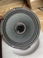
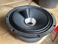
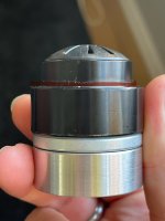
Sure is, I managed to get good measurements of the throat of the redcatt coaxial by knocking it of its glue joint so v2 as I showed in the image is printing right now. With a nicer fitting against the metal.
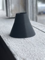
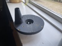
This test print of the surfaces that will touch fits really nice.
This test print of the surfaces that will touch fits really nice.
Attachments

A big tip for co-entrant style multiple-entry horns;
The holes will f*ck up the hf response badly because of all the internal reflections.
This can be solved for a very large part by covering the mid-holes with an acoustic mesh (like a gore acoustic vent https://www.gore.com/products/gore-acoustic-vents-industrial-applications) with just about the right acoustic resistance (use the lumped part of abec to test this) to be "open" for the mid frequencies while being "closed " for the HF.
The membrane should be reactive, not resistive (meaning not porous)
hint; even a bit of painters masking tape could work..
Kees
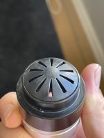
Absolutely true in what you say. I have tried using open cell foam from phase plug of the tweeter and up to the ports and I plan to try going beyond the ports as well.
But you gave me an idea. I will print a thin insert like the one in the photo but without any opening to see the effect with and without the midrange insertion ports in real life.
But you gave me an idea. I will print a thin insert like the one in the photo but without any opening to see the effect with and without the midrange insertion ports in real life.
Attachments
Thanks a lot for the link, I thought about the possibility with a Mesh sometimes, but never found the right product for deeper researchA big tip for co-entrant style multiple-entry horns;
Daniel
I bought some really fine mech nylon sieve material way back, but I never took my time to measure the impact of sound passing thru. Maybe my coentrant driver will function as a test bed for the future.
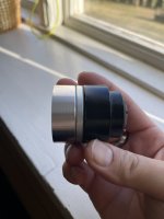
Adapter for the SB Audience ROSSO-65CDN-T:


This is the idea.

This is the idea.
Last edited:
Love it!Adapter for the SB Audience ROSSO-65CDN-T:
View attachment 1309749 View attachment 1309750
This is the idea.
View attachment 1309753
The h108 has a 31 deg exit; would such an adapter be a an advantage over the «standard» you have already developed for the h108?
Sure. I'm also going to print and measure all of it, hopefully soon.I suppose you have access to this CD!?
It's much easier to work with a driver likeSure is, I managed to get good measurements of the throat of the redcatt coaxial by knocking it of its glue joint so v2 as I showed in the image is printing right now. With a nicer fitting against the metal.
This test print of the surfaces that will touch fits really nice.
https://www.bcspeakers.com/en/products/coaxial/6-5/8/6hcx51
since it has a larger voice coil and much more space to play around with.
This is something I'm working on at the moment:
I've had some success with this Oberton driver as it has a very shallow wide angle "adapter"
The tricky part is that a lot of these smaller compression driver can't play very low and you kind of want them to go down to 1k
Maybe a better way of doing it will be using a coax with a tweeter and making a phase plug on that 🙂
Kind of what PHL offer...
They also have woofers with just holes, so you can attach your own CD on it.
Maybe you can even try to remove the aluminum piece in your driver, as it should have no effect on the magnetic field.Sure is, I managed to get good measurements of the throat of the redcatt coaxial by knocking it of its glue joint so v2 as I showed in the image is printing right now. With a nicer fitting against the metal.
This test print of the surfaces that will touch fits really nice.
Well this piece is part of the motor structure with steel and also a magnet so it’s not something one should remove.
And @aragorus funny you should mention Oberton. https://www.oberton.com/en/products/neodymium-coaxials/467-10ncx.html?showall=1 this one have a nice compression driver with composite membrane.
Bucket list driver for me and these types of builds.
And @aragorus funny you should mention Oberton. https://www.oberton.com/en/products/neodymium-coaxials/467-10ncx.html?showall=1 this one have a nice compression driver with composite membrane.
Bucket list driver for me and these types of builds.
Attachments

I have Beyma 5'' coax it on my shelf and even the first couple prototypes of combining drivers into a single throat (not successful yet). But... maybe it would be better to talk about Coax-MEH in a separate thread?
Greetings all,
can the documentation for printing provided by @mabat be used for (accurate) determination of dimensions?
The reason for my question is having a driver with unusual - threaded - mount (RCA 1428B), and as such I would have to design and print my own adapter. Consequently, I would need the dimension associated with the horn flange, including the initial angle and diameter of the input.
Kindest regards,
M
I think there's no reason why you couldn't simply trace the contours of the STLs, as most CAD products probably have an STL import function. The STLs themselves are as accurate as it gets.
My recommendation would be to start with a suitable existing adapter and only modify the mounting, preserving the air path, if possible. They are all optimized and deviating from that can lead to a degraded result. Or, you can provide a drawing of the driver and I can try to make an adapter for that specific case - this is the whole idea after all.
I think I can add .DXF contour files and the associated drawings to the packages.
Last edited:
R-OSSE is entered inside curly braces like this:
If you include a Rot parameter for a R-OSSE it comes after the ending curly brace. In contrast, OSSE looks like this:
R-OSSE is for freestanding horns so you'd want to use ABEC.SimType in free space. If your horn is axisymmetric (basic round horn) you can also use the CircSym profile to speed up the ABEC simulations.
If you have trouble generating your STL after simulating your horn try commenting ABEC.SimProfile line out with a semi-colon ( ; ) and also set Output.ABECProject to zero like this:
R-OSSE = {
R = 45
a = 54
r0 = 9
a0 = 36
m = 0.76
r = 0.28
q = 3.65
k = 14;
b = 0.2
arcterm = 160
}
Rot = 2
If you include a Rot parameter for a R-OSSE it comes after the ending curly brace. In contrast, OSSE looks like this:
Throat.Diameter = 9 ; [mm]
Length = 75 ; [mm]
Throat.Angle = 0 ; [deg]
Coverage.Angle = 42 ; [deg]
OS.k = 0.5
Term.s = 0.5
Term.q = 0.996
Term.n = 2
Rot = 0
R-OSSE is for freestanding horns so you'd want to use ABEC.SimType in free space. If your horn is axisymmetric (basic round horn) you can also use the CircSym profile to speed up the ABEC simulations.
ABEC.SimType = 2 ; 2= Free Space, 1= Infinite Baffle
ABEC.SimProfile = 0 ; 0 = CircSym (comment out when creating STLs)
If you have trouble generating your STL after simulating your horn try commenting ABEC.SimProfile line out with a semi-colon ( ; ) and also set Output.ABECProject to zero like this:
Output.SubDir = ""
Output.STL = 1
Output.ABECProject = 0
- Home
- Loudspeakers
- Multi-Way
- Acoustic Horn Design – The Easy Way (Ath4)