Glad to help!🤓 While my ramblings are not very scientific its certainly lot of fun to me to think about the stuff, and very nice if they are helpful to advance your /others thought processes. Hopefully errors are noticed and corrected, science brought in and so on. Sharing
Yeah seems logical. The pluck would be most effective for mouth reflection as it would yield a secondary sound that spends longest time within the foam. Perhaps there is some throat related phenomena that also spends more time in the device than direct sound, from diffraction slot or something. If the foam pluck went all the way back to the drivers conical exit section and helped attenuate some reflection that happens on the driver / waveguide junction, perhaps that's effective as well.So with a reflection-free mouth the foam has typically a very little merit, hasn't it?
Conversely, if we have a waveguide with smooth profile all the way then there shouldn't be any modes that would benefit from a foam pluck. If polar plot is clean in simulator, by clean I mean without signs of interference, I would say then there is less need for a foam pluck. Reality is complicated though, perhaps foam pluck makes always better device 🙂
Last edited:
This is by far the fastest approach to test all the different things - as a free-standing R-OSSE in circular symmetry mode.

This is the effect of the dome depth (6, 7, 8 mm). Seems it pretty much sets the beamwidth above 10 kHz.


This is the effect of the dome depth (6, 7, 8 mm). Seems it pretty much sets the beamwidth above 10 kHz.
Code:
R-OSSE = {  ; R-OSSE/ATH-DOME
  R = 120.0
  r0 = 19
  a0 = 40
  a = 55
  k = 0.7
  r = 0.3
  b = 0.8
  m = 0.7
  q = 3
}
Source.Contours = {  ; Bliesma T34B
  dome WG0 34 7 2 -1 5 1
}
Source.Velocity = 2

Mesh.AngularSegments = 8
Mesh.LengthSegments = 40
Mesh.SubdomainSlices =
Mesh.WallThickness = 5

ABEC.MeshFrequency = 32000
ABEC.NumFrequencies = 60
ABEC.SimProfile = 0
ABEC.SimType = 2
ABEC.f1 = 500
ABEC.f2 = 20000

ABEC.Polars:SPL = {
  MapAngleRange = 0,180,37
  Distance = 1       ; [m]
  NormAngle = 0
}

Output.ABECProject = 1
Output.STL = 0

Report = {
  Title = "ATH-DOME-T34B"
  Width = 1280
  Height = 800
  NormAngle = 5
  ;GnuplotCode = dome.gpl
  MaxAnglePM = 120
}This, to me, is closest to my explanation. In a flat baffle source the edges will leak out the sound as there is free space beyond (a pressure release boundary.) With a waveguide you have walls (zero horizontal velocity and hence higher pressure,) resulting in an increase in SPL at the edges.It is my understanding that the waveguide simply helps to build up the pressure towards the sides of the diaphragm, which alone is not capable of, due to its axial motion. With a waveguide there's less volume for the available velocity.
Your second paragraph is dead on.I'm not sure what the higher order modes are, zeroth order mode would be "direct sound" and any mode past that would be any reflected/diffracted wave at any point, just mode higher than 0?
The foam pluck would be effective when the secondary sounds, a reflection or diffraction back wave travel a long way in it, much longer than the direct sound. For example diffraction from horn mouth back to the device and then out again has traveled two times the distance within the foam than direct sound, spent more time in it attenuating more.
As to the first, there are dozens (in theory an infinite number) of different propagation modes for any waveguide. What you want is just the 0 one. But in all waveguides modes 1,2,3,... get permissible as the wavefront propagates. Waveguide design is a process that maximizes the 0 order and minimizes the higher order modes (HOM).
Here is nice toy to visualize the specular reflections from a single point source, like how energy going towards off-axis would reflect, from tip of a dome. https://www.desmos.com/calculator/c8ztwedwof
Orange lines are equal path length for sound starting from point source, here for four cycles at 20kHz. Blue vectors represent single wavelength at 20kHz and where the direct sound has gone with same wavelength, leading about one wavelength in this example. When there is gap between the two the reflected sound is delayed more or less. If the gap is about half the blue vector there would be dip that direction, and when the lines meet there would be boost.
Not sure how much any of it translates to reality but might be fun to zone in to some visuals, then try that on ABEC and see if there is any correlation 🙂
Here Mabats example above
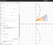
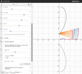
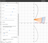
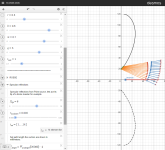
Example of flat baffle and sound escaping 🙂
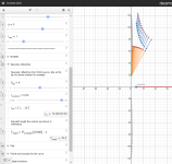
Orange lines are equal path length for sound starting from point source, here for four cycles at 20kHz. Blue vectors represent single wavelength at 20kHz and where the direct sound has gone with same wavelength, leading about one wavelength in this example. When there is gap between the two the reflected sound is delayed more or less. If the gap is about half the blue vector there would be dip that direction, and when the lines meet there would be boost.
Not sure how much any of it translates to reality but might be fun to zone in to some visuals, then try that on ABEC and see if there is any correlation 🙂
Here Mabats example above


Example of flat baffle and sound escaping 🙂

There is always some higher order effects even in ideal situations and hence the foam will always do something. The cost/tradeoffs are quite acceptable to me. It's a few dB loss at the very highest frequencies and almost nothing at the low end. With plenty of headroom to spare what's not to like. But sure the foam gets less and less effective for better and better waveguides. Where the turning point is between worthwhile and not is likely difficult to find. For my waveguides it's certainly worthwhile.Yeah, that sounds quite reasonable (again)...
I should ask you more often.
- So the foam plug is actually much more effective for the mouth-related issues than the throat-related. I don't know why but I always assumed it the other way around. So with a reflection-free mouth the foam has typically a very little merit, hasn't it?
STL for those who want to give it a quick try.
https://a360.co/3IoTu1O


https://at-horns.eu/ext/ATH-DOME-T34B-V1.zip
https://a360.co/3IoTu1O
https://at-horns.eu/ext/ATH-DOME-T34B-V1.zip
For anyone testing, be cautious of the glued on surround on the Bliesma drivers, clamping the waveguide straight onto this can cause problems.STL for those who want to give it a quick try.
I created an STL spacer to print to stop that from happening, it is included in a small waveguide for the T34A that I posted
https://www.diyaudio.com/community/...uides-for-cnc-3d-printing.318190/post-7171815
I don't quite understand the issue, haven't had these tweeters in my own hands, but sure do whatever it takes...
The Surround is glued on the faceplate and extends quite some distance. If you don't have a spacer the waveguide can crush the surround when it is attached. These drivers are expensive enough to want to avoid repeating mistakes others have made before. Image of the silk tweeter below to demonstrate.

Yes essentially but it is part of a single piece of fabric that the surround is formed of. If you clamp the glued on flat bit too close to the moving part it can cause damage with excursion. Given that a single layer printed ring or cut piece of thin cardboard avoids the problem I just thought I would point it out.
Just an affirmation - is the surround on the T34B really concave (as in the drawing)?
Or could it happen that they changed it to convex recently?

I've seen only photos and it's surprisingly hard to tell.
Or could it happen that they changed it to convex recently?
I've seen only photos and it's surprisingly hard to tell.
Thanks Mabat - is this meant to be used as a press-fit?STL for those who want to give it a quick try.
https://a360.co/3IoTu1O
View attachment 1175790 View attachment 1175791
https://at-horns.eu/ext/ATH-DOME-T34B-V1.zip
- Home
- Loudspeakers
- Multi-Way
- Acoustic Horn Design – The Easy Way (Ath4)