
I saw many tweeter companies do this kind of thing way back. I thought that it was quite common.
I mean that a shallow waveguide on a dome tweeter is a common design. For the obvious reasons that you show.
Yeah, especially in the smaller studio monitors, that's almost a standard now. Maybe still not so much in home hi-fi, but that was always all over the place...
- I just wanted to see what beamwidth I'm able to get with an "ordinary" waveguide, as the Purify Audio guys showed +-70deg up to 20kHz recently, which is really not common...
- I just wanted to see what beamwidth I'm able to get with an "ordinary" waveguide, as the Purify Audio guys showed +-70deg up to 20kHz recently, which is really not common...
Last edited:
Any idea what I may be doing wrong? I'm using the latest build for ATH. I'm literally running the exact code included in the following post: 9,879
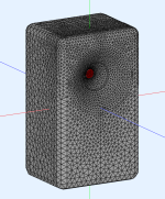
However, for me, the LF driver is not showing up in ABEC (See picture below) ? Is there something I need to enable to view in ABEC?
Apologies for the newbie questions I'll be (*have been) asking. I left this thread a while ago and its exploded since then 🙂 (in a good way, of course). So many new features.
My near-term goal is to simulate a waveguide for the Peerless DA25TX with an 8" driver (like the Dayton Audio RS225-8).
The following is the code I'm starting with. Please note - there are many features I don't understand:
| ; ATH-DOME Template ; ------------------------------------------------------- ; Peerless DA25TX00-08 OSSE = { r0 = 16 a0 = 40 k = 0.7 a = 55 L = 26 s = 1.27 n = 2.15 q = 0.996 } Source.Contours = { dome WG0 26 5.6 3 1.5 4 1 } Source.Velocity = 2 ; axial motion Mesh.Enclosure = { Spacing = 90,70,90,350 Depth = 200 EdgeRadius = 35 ; 25 EdgeType = 1 FrontResolution = 8,8,16,16 BackResolution = 20,20,20,20 LFSource.Below = { Spacing = 10 Radius = 82 DrivingWeight = 1 SID = 1 } } Mesh.VerticalOffset = 80 Mesh.Quadrants = 14 ; =14 for 1/2 symmetry Mesh.LengthSegments = 24 Mesh.AngularSegments = 64 Mesh.ThroatResolution = 3 Mesh.MouthResolution = 9 Mesh.SubdomainSlices = Mesh.ZMapPoints = 0.3,0.2,0.7,0.9 ;Mesh.InterfaceResolution = 6 ;Mesh.RearResolution = 20 ; ------------------------------------------------------- ABEC.SimType = 2 ABEC.MeshFrequency = 1000 ; [Hz] ABEC.NumFrequencies = 40 ABEC.f1 = 1500 ; [Hz] ABEC.f2 = 20000 ; [Hz] ABEC.Polars:SPL = { MapAngleRange = 0,90,10 Distance = 2 ; [m] NormAngle = 0 } ; ------------------------------------------------------- Report = { Title = "ATH-DOME" NormAngle = 10 Width = 1400 Height = 900 } Output.STL = 0 Output.ABECProject = 1 |
Attachments
Last edited:
Change "Below" to "B". That's my bad, I don't know why I changed that.
And that did it! Thank you, @mabat! Can I ask a few questions (pertaining to code I could find in the manual):
1) What does "SID = 1" mean under LFSource?
2) For dome geometry, what do numbers represent?
For example dome WG0 26 5.6 3 1.5 4 1 <<-- so 26mm is the dome diameter?, 5.6mm is the dome height? 3mm is the surround width? and I have no clue what 1.3 4 1 represents. I'm not even sure I got the first three numbers right. I figured the 26mm + 2 x 3mm surround width = 32mm overall diameter, and thus I selected waveguide mouth radius to be 16mm.
3) What does "Mesh.InterfaceResolution =" represent?
4) What does "Mesh.VerticalOffset =" represent?
I tried to look up some of the items above in the manual, but I realize (and understand) that the application is developing at a faster speed and that obviously poses a challenge to keep updating the manual
1) Try the code here: https://www.diyaudio.com/community/...-design-the-easy-way-ath4.338806/post-7169897
2) https://www.diyaudio.com/community/...-design-the-easy-way-ath4.338806/post-7353694
3) It's the mesh resolution of a subdomain interface surface, if any.
4) https://www.diyaudio.com/community/...-design-the-easy-way-ath4.338806/post-7169912
2) https://www.diyaudio.com/community/...-design-the-easy-way-ath4.338806/post-7353694
3) It's the mesh resolution of a subdomain interface surface, if any.
4) https://www.diyaudio.com/community/...-design-the-easy-way-ath4.338806/post-7169912
Hi. I would like to play with bliesma T25B simulations like you did with T25A and T34B. Does someone know if T25B geometry is the same than T25A ?
Thanks.
Thanks.
That can be difficult 🙂
I'm still trying to find out the actual shape of the surround of T34B (concave/convex) and there's so much conflicting information that I think I will have to buy me a pair to check it myself...
- Fortunately it seems that the surround itself doesn't make a night and day difference. It's really the dome shape that has a profound effect at HFs.
Last edited:
Change the dome height to 4.24mm, everything else remains the same.Does someone know if T25B geometry is the same than T25A ?
I have found something I quite like for the T34A, it is harder to get right than the B version. The simulation conditions seem to matter much more than I found previously.


Yes, that's why I haven't shared an IB script at all - it's really not much helpful with these designs.The simulation conditions seem to matter much more than I found previously.
Free-standing axisymmetric (R-OSSE) can be pretty close to a rounded enclosure though - it can save quite a lot of time during iterations. Baffle-mounted version (OSSE) can then be derived from that.
Last edited:
Still makes quite a difference above 8K, but I suspect that is also dependent on the dome it is attached to.- Fortunately it seems that the surround itself doesn't make a night and day difference. It's really the dome shape that has a profound effect at HFs.
Attachments

Yeah, but it's a smooth change and nothing really dramatic, IMO. It's still only 1 - 2 dB...
Last edited:
Yep, nothing to cause you to buy a driver based on that alone, but enough to change the ideal profile.
Convex out inverted in 🙂 Concave surround has more HF output than convex.
Convex out inverted in 🙂 Concave surround has more HF output than convex.
Anyway, this is almost +-70 deg up to 20 kHz 🙂
So it's possible with the right shape of the dome - obviously it must be deep enough for that, which the T34A is.
So it's possible with the right shape of the dome - obviously it must be deep enough for that, which the T34A is.
Apologies if this has been asked before and/or if the answer is obvious, but cannot easily find answer to following (and it is not obvious to me):
- A concave shaped horn (like JBL's have) helps with increasing sound pressure for certain frequencies and helps with making directivity more constant - correct? Most waveguides (shallow or deep) seem to use the concave shape.
- What is the effect of a convex shaped waveguide vs a concave one? For example Neumann's KH420 seems to use convex shaped waveguides for tweeter and mid domes. How does this effect pressure and / or directivity?
I think all waveguides and horns are actually convex (concave would be e.g. a parabolic shape - a disaster as a horn). Maybe you mean something else, but I don't see what it is... Can you show an example of what you mean exactly?
- BTW, I think this pretty much makes all the smaller tweeters obsolete...
Why would anyone use a smaller tweeter now? Certainly not for a wider radiation pattern any more. A smoother response/even higher breakup perhaps, but these 34mm tweeters are already so good that I doubt that it would have a merit.
Last edited:
- Home
- Loudspeakers
- Multi-Way
- Acoustic Horn Design – The Easy Way (Ath4)