OK, so the terms were used correctly, this can be understood as convex and concave, but the situation on the right actually never happens (that would lead to a very poor acoustic performance). The wall can be flat, but never more "concave" than that. And flat is generally not the best option, as any good horn needs a gradual termination into the air - you simply have to start bending the walls somewhere (and more gradual is typically found to be better), so it's always convex in the end...
Last edited:

Waveguides in attached pic (well regarded and very well measured pro monitor Neumann KH420) are convex, right?
It might be concave in the end (only small portion of the waveguide, like you say to give a gradual termination in air), but it starts convex.
Has it been established how this kind of waveguide (convex) influences response and directivity VS a purely concave waveguide? (all other things being equal).
Attachments
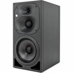
Yes, it is convex, all the way through. Seems to me as flat for the most part, with some simple mouth edge rounding.
But as was said, there are no "purely concave" waveguides, so I don't understand the question.
The measurement tells you the whole story, there's really nothing more you would need to make a judgement. I'm not familiar with those speakers, so I don't know what more to say...
But as was said, there are no "purely concave" waveguides, so I don't understand the question.
The measurement tells you the whole story, there's really nothing more you would need to make a judgement. I'm not familiar with those speakers, so I don't know what more to say...
Thank you for trying to answer my question. It is clear I should get more educated and find a better way to ask.
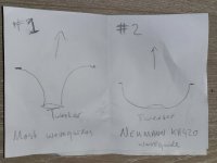
From my drawing, #1 seems to be how most waveguides and tweeter horns are shaped (narrow start, widening towards the exit). Which I thought was called concave.
Drawing #2 seems to be the exception, a wide start with a narrowing angle towards the exit (which I thought was called convex). At least one reputable loudspeaker manufacturer seems to adopt this shape (Pic in my last post).
Because shape #1 and #2 are very different, I was wondering how their acoustical effects relate to each other. Because these effects are not always intuitive for laymen, I thought I should ask here. If I were to design my own loudspeaker, I wonder for which requirements I should use one shape over the other. With my current knowledge, that is the best way I can ask.
The most honest answer I know is that there are no simple rules. Look at the waveguides for the Bliesma tweeters presented above - would I guess that they provide a more or less constant beamwidth 1k - 20k just by looking at them? No.
Well, there are some rules - I'd suggest to start experimenting with Ath/ABEC and find out much more yourself. Nothing can subsitute that.
Well, there are some rules - I'd suggest to start experimenting with Ath/ABEC and find out much more yourself. Nothing can subsitute that.
Well so much for shortcuts then🙂 And thank you for the honest answer. Slightly disheartening though that even for experts, some matters remain unintuitive (simulate-able and solvable yes, but still unintuitive).
You seem to be under the impression that the Neumann waveguides are shaped like your #2 drawing - they aren't.Drawing #2 seems to be the exception, a wide start with a narrowing angle towards the exit (which I thought was called convex). At least one reputable loudspeaker manufacturer seems to adopt this shape (Pic in my last post).
Neumann has a downloadable 3D model of the KH80 on their site, for example. Opening that will reveal a waveguide that is almost conical (very slight flare) until the mouth roundover. The fact that they look the way you explain is a trick of the eye, not reality. I agree that it sort of looks that way though.
These are fantastic results Fluid! May i ask what the boundary conditions are here? Quarter or half symmetry in a box, perhaps an axisymmetrical freestanding waveguide?I have found something I quite like for the T34A, it is harder to get right than the B version. The simulation conditions seem to matter much more than I found previously.
I am asking because I've been going on and off for the past 2 years or so trying to make a waveguide for the Peerless DA32TX, but I can't seem to make it behave. My personal best guess is that the combination of a relatively large surround and tall dome is creating difficulties. I actually ended up scrapping the idea of using the DA32TX altogether and went for a T25B, which was much simpler to design for. I still have the DA32TX laying around, so I occasionally dabble in trying to make it work, without any luck.
Quarter symmetry free space.
Tall domes are tricky, I had a lot of trouble trying to find a good profile and had settled on a very shallow one. Turns out it needs to be very wide to work, which is not the direction I was trying.
Picture number 2 is very much like a parabolicApologies, I must be using wrong terminology. Does the picture help?
https://www.diyaudio.com/community/threads/hornresp.119854/page-620#post-6780391
Well put.OK, so the terms were used correctly, this can be understood as convex and concave, but the situation on the right actually never happens (that would lead to a very poor acoustic performance). The wall can be flat, but never more "concave" than that. And flat is generally not the best option, as any good horn needs a gradual termination into the air - you simply have to start bending the walls somewhere (and more gradual is typically found to be better), so it's always convex in the end...
I was once asked how to do an ideal waveguide - theoretically. I simply said to start with any shape you want (Throat/mouth) and then start modifying/smoothing until you have minimized the 2nd derivative of the shape (including any edges like at the mouth for instance.) From what I see here that is probably not far from reality.
That's what the ATH DOME profile is for and it takes minutes in Ath:
1) sketch both horizontal and vertical profiles (OSSE curves) to your liking: https://www.desmos.com/calculator/ddnk9y2c1f
2) enter the parameters into an Ath script (see an example of a full script below)
You only can't simulate more than one WG at once, that's the current limitation. You would have to merge them together in a CAD (out of scope of this hint).
Code:
; ATH-DOME Template
; -------------------------------------------------------

_OSSE = {  ; horizontal
  r0 = 25
  a0 = 40
  a = 55
  k = 0.3
  L = 50
  s = 0.6
  n = 2.15
  q = 0.998
}

_OSSE = {  ; vertical
  r0 = 25
  a0 = 40
  a = 40  ; <---
  k = 0.3
  L = 50
  s = 0.3  ; <---
  n = 2.15
  q = 0.998
}

; now let's make an elliptical blend:
OSSE = {
  r0 = 25
  a0 = 40
  a = 55 - 15*sin(p)^2
  k = 0.3
  L = 50
  s = 0.6 - 0.3*sin(p)^2
  n = 2.15
  q = 0.998
}

Source.Contours = {
  dome WG0 42 10 4 -2 5 2
}

; the rest is as usual...

Source.Velocity = 2   ; axial motion

Mesh.ZMapPoints = 0.3,0.2,0.7,0.9

Mesh.Enclosure = {
  Spacing = 40,50,40,200
  Depth = 200
  EdgeRadius = 35
  EdgeType = 1
  FrontResolution = 8,8,16,16
  BackResolution = 20,20,20,20

  _LFSource.Below = {
    Spacing = 10
    Radius = 75
    DrivingWeight = 1
    SID = 1
  }
}

Mesh.Quadrants = 1        ; =14 for 1/2 symmetry
;Mesh.VerticalOffset = 80

Mesh.AngularSegments = 64
Mesh.LengthSegments = 14
Mesh.SubdomainSlices =

Mesh.ThroatResolution = 3
Mesh.MouthResolution = 9
Mesh.InterfaceResolution = 6
Mesh.RearResolution = 20

ABEC.SimType = 2
ABEC.f1 = 1500   ; [Hz]
ABEC.f2 = 20000  ; [Hz]
ABEC.NumFrequencies = 40
ABEC.MeshFrequency = 1000   ; [Hz]

ABEC.Polars:SPL = {
  MapAngleRange = -120,120,49
  Distance = 1      ; [m]
  NormAngle = 0
}

Report = {
  Title = "ATH-DOME"
  NormAngle = 10
  Width = 1400
  Height = 900
}

Output.STL = 0
Output.ABECProject = 1
Last edited:
You can try what fluid did, i.e. take the ATH DOME profile template and try changing the coverage angle (alpha) and length (L). Maybe you will have more luck, maybe not.I actually ended up scrapping the idea of using the DA32TX altogether and went for a T25B, which was much simpler to design for. I still have the DA32TX laying around, so I occasionally dabble in trying to make it work, without any luck.
While I've been following this thread closely for many years, I have never actually used ATH/ABEC. I draw my waveguides using Fusion360 and then simulate in AKABAK. My approach has generally been similar to what you're proposing, however.
I've made a model of the dome to the best of my abilities, but measuring these things can be tricky. The T25B was a lot easier in that regard, as Stanislav was kind enough to share dome/suspension drawings with me.
As a followup question, what kind of weighting do people generally give the suspension. I've been splitting it in half and giving the inner part 0.75x amplification and the outer part 0.25x amplification (I believe that was mentioned as a good compromise earlier in this thread sometime).
That's also what I do (the "dome" macro in Ath does it automatically) but have never made any further analysis, so I can't say whether it is the optimal approach.I've been splitting it in half and giving the inner part 0.75x amplification and the outer part 0.25x amplification
If he put the drawings on the website he would save a lot of time, it seems 🙂The T25B was a lot easier in that regard, as Stanislav was kind enough to share dome/suspension drawings with me.
If you want to you can use Ath derived profiles in your existing work flow. I do this myself sometimes, export the Grid Coordinates to generate the waveguide surface and combine it with other geometry.I draw my waveguides using Fusion360 and then simulate in AKABAK.
I have to admit that I still have trouble understanding what does it mean to minimize the 2nd derivative of a shape. How would you define it? We have a curve y(x) with its 1st and 2nd derivatives (y'(x) and y''(x), that together determine the curvature k(x)). But how do you express the 2nd derivative for a curve as a whole, to know it has been minimized?I was once asked how to do an ideal waveguide - theoretically. I simply said to start with any shape you want (Throat/mouth) and then start modifying/smoothing until you have minimized the 2nd derivative of the shape (including any edges like at the mouth for instance.)
Last edited:
Isn't "minimizing second derivative" just minimizing change in rate of change? in other words getting rid of abrupt changes in curvature?
sorry disrupting, thinking out loud, taking maximum of second derivative would be "the most abrupt change", right? so keeping the max as low as possible would be the goal then and for example for circular arc this would be 0 until the end? Minimum second derivative all the way around the construct or just up until mouth or something?
sorry disrupting, thinking out loud, taking maximum of second derivative would be "the most abrupt change", right? so keeping the max as low as possible would be the goal then and for example for circular arc this would be 0 until the end? Minimum second derivative all the way around the construct or just up until mouth or something?
Last edited:
- Home
- Loudspeakers
- Multi-Way
- Acoustic Horn Design – The Easy Way (Ath4)