Yes, that's due to the bigger throat. How exactly it will look in real depends on the driver and its exit wavefront - the "better" the driver, the more it will match the simulation.I guess the things above 11k are given by the 1.4" throat size, am I correct?
You could make the DI rise more gradual, at the price of making it rising across a wider frequency range. There's yet no definitive answer to what is better.

What is wrong here? I still get
error: polar map 'SPL_H_T' not found in the results
I also think treating OSB as the minor wood it is, making it suffer from a bright DI, could still turn on you as bad karma, @pelanj. Watch out!
error: polar map 'SPL_H_T' not found in the results
ABEC.Polars:SPL_H_W = {
MapAngleRange = -180,180,72
Distance = 2.0
NormAngle = 0
Offset = 66
FRDExport = {
NamePrefix = hor woofer
PhaseComp = -2.0 ;[m]
}
}
ABEC.Polars:SPL_V_W = {
MapAngleRange = -180,180,72
Distance = 2.0
NormAngle = 0
Inclination = 90
Offset = 66
FRDExport = {
NamePrefix = ver woofer
PhaseComp = -2.0 ;[m]
}
}
ABEC.Polars:SPL_H_T = {
MapAngleRange = -180,180,72
Distance = 2.0
NormAngle = 0
Offset = 66
FRDExport = {
NamePrefix = hor tweeter
PhaseComp = -2.0 ;[m]
}
}
ABEC.Polars:SPL_V_T = {
MapAngleRange = -180,180,72
Distance = 2.0
NormAngle = 0
Inclination = 90
Offset = 66
FRDExport = {
NamePrefix = ver tweeter
PhaseComp = -2.0 ;[m]
}
}
I also think treating OSB as the minor wood it is, making it suffer from a bright DI, could still turn on you as bad karma, @pelanj. Watch out!
Have you gotWhat is wrong here? I still get
error: polar map 'SPL_H_T' not found in the results
Report = {
Title = <title>
PolarData = <polar_tag>
Where polar_tag is the same as the name you have given somewhere in your script? e.g. SPL_H_T
No, I didn’t know that was required, thanks. I had not understood that remark by mabat when he pointed me to it the first time.
Under the ath report tag?
Under the ath report tag?
Last edited:
Yes have a look at the reporting section of the manual it explains all the options, there could be something in there to help with the other glitch you were experiencing.No, I didn’t know that was required, thanks. I had not understood that remark by mabat when he pointed me to it the first time.
Under the ath report tag?
@mabat, I think there might be an error on page 4 of https://at-horns.eu/release/R-OSSE Waveguide.pdf. I think y2(L) should be y2(1).

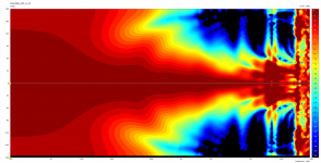
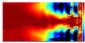
Took me a while to generate clean export. And some things have well changed:

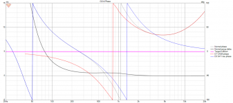
This is based on a LR24 LP @ 1.3k and a Bessel 24 HP @1.2k. XO is not even closely in phase, but gives the best summation for Power and DI with a flat LW. One thing that comes with this is that the axis center is actually shifted by about 10 degrees down, I do not really appreciate that:
.png")
.png")
I had entered an offset for the length of the waveguide, but it was not displayed in ABEC3.

Also, when I enter an offset with the offset parameter, must this be added/subtracted from phase compensation?
This is based on a LR24 LP @ 1.3k and a Bessel 24 HP @1.2k. XO is not even closely in phase, but gives the best summation for Power and DI with a flat LW. One thing that comes with this is that the axis center is actually shifted by about 10 degrees down, I do not really appreciate that:
I had entered an offset for the length of the waveguide, but it was not displayed in ABEC3.
Also, when I enter an offset with the offset parameter, must this be added/subtracted from phase compensation?
Attachments

Tick the Spectrum Hints item in the view options panel on the right, that will show you where the measurement is being taken from. The axis going through the speaker is about how the meshes are positioned.I had entered an offset for the length of the waveguide, but it was not displayed in ABEC3.
This is what it's all about. Forget about the phase itself, it only has to be correctly calculated&used. Whatever comes best in the overall amplitude and power, take it.XO is not even closely in phase, but gives the best summation for Power and DI with a flat LW.
All the polars exported must use the same setting, that's the only requirement (besides a reasonable point of rotation itself). You can use the manual phase compensation to eliminate the major part of the propagation delay so the phase data look nicer. Again, the same value in all the polar definitions. The exact value itself is not important.Also, when I enter an offset with the offset parameter, must this be added/subtracted from phase compensation?
Did you try? I think it should be y2(L) but frankly it's a formulation I don't use anywhere else so I'm not sure now.I think y2(L) should be y2(1).
Looking at the picture, perhaps you could try to set an additional small delay for the WG source (manually in observation.txt) because with a CD there will be some additional delay due to the diaphragm to throat distance. With the woofer, I'm not sure.
- You can probably do it in the crossover simulator, should give the same result.
Last edited:
Ah, you are probably right. I changed y2(tL) to y2(t) in the last revision and forgot to change this. Thanks!Did you try? I think it should be y2(L) but frankly it's a formulation I don't use anywhere else so I'm not sure now.
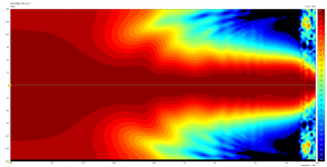
I have noted a little complication, when I had a look at the shifting of the reference axis due to my crossover attempt: Up is down and down is up! It is also visible (only now to me) from the VCAS output that I had posted in my previous post. Woofer axis is shifted upward, tweeter downward, where it should be the other way round. Muting the woofer in VCad shows the main vertical baffle diffraction caused by the downward enclosure pointing up:
1_noXO.png")
I had used the following ath parameters to generate spectra:
Is there a way to solve this internally? To my eyes I figure that both woofer and tweeter are mirrored, I could rename them in this case. But I'd rather like to double check before I rely something on this.
Regards
I had used the following ath parameters to generate spectra:
ABEC.Polars:SPL_H_W = {
MapAngleRange = -180,180,72
Distance = 2.0
NormAngle = 0
Offset = 66.5
FRDExport = {
NamePrefix = hor woofer
PhaseComp = -2.0
}
}
ABEC.Polars:SPL_V_W = {
MapAngleRange = -180,180,72
Distance = 2.0
NormAngle = 0
Inclination = 90
Offset = 66.5
FRDExport = {
NamePrefix = ver woofer
PhaseComp = -2.0
}
}
ABEC.Polars:SPL_H_T = {
MapAngleRange = -180,180,72
Distance = 2.0
NormAngle = 0
Offset = 66.5
FRDExport = {
NamePrefix = hor tweeter
PhaseComp = -2.0
}
}
ABEC.Polars:SPL_V_T = {
MapAngleRange = -180,180,72
Distance = 2.0
NormAngle = 0
Inclination = 90
Offset = 66.5
FRDExport = {
NamePrefix = ver tweeter
PhaseComp = -2.0 ;[m]
}
}
Is there a way to solve this internally? To my eyes I figure that both woofer and tweeter are mirrored, I could rename them in this case. But I'd rather like to double check before I rely something on this.
Regards
Yes, it's upside down. I haven't figured out how to reverse it yet; maybe the plane orientation, I don't know. Maybe fluid knows already.
Probably I will just add an option of reversing in the FRDExport.
Probably I will just add an option of reversing in the FRDExport.
Last edited:
I'm also having troubles with the x values. I can't get them to match with the earlier formulae. Glancing over the formulae gives me the impression they are different and I implemented both and I get different results. I haven't done the hard labour yet, but I suspect the L scaling...
Flip the MapAngleRange to 180,-180, 72 and it should go the other way. Starting at plus 180 going round to -180.Yes, it's upside down. I haven't figured out how to reverse it yet; maybe the plane orientation, I don't know. Maybe fluid knows already.
Probably I will just add an option of reversing in the FRDExport.
I made some silly mistakes in the document, this is how it should be: https://www.desmos.com/calculator/redw2gvf9eI'm also having troubles with the x values. I can't get them to match with the earlier formulae. Glancing over the formulae gives me the impression they are different and I implemented both and I get different results. I haven't done the hard labour yet, but I suspect the L scaling...
(Alternatively: https://www.desmos.com/calculator/4xnabjmxm6)
Good to know. The Spectrum Hints follow the offset.Tick the Spectrum Hints item in the view options panel on the right, that will show you where the measurement is being taken from. The axis going through the speaker is about how the meshes are positioned.
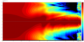
This visualization is dedicated to mabat, and his arguments against a baffled device. Negative angles in front, we are seeing the disruption of vertical respose due to the enclosure below the waveguide:
versus up
Obviously, this can still make for a good system performance, but from a perspective of absolute performance, the baffle obviously has a detrimental effects within a +- 90 degree window up to 20k.
Well the truth is that the vertical performance suffers even with a free standing WG. I already made some quick simulations, then I had to concentrate on other stuff. So it's not a universal cure. I don't know yet the extent to which it's better or worse than all-in-one box. This all is to be found out.
Last edited:
- Home
- Loudspeakers
- Multi-Way
- Acoustic Horn Design – The Easy Way (Ath4)