when trying to model a midrange waveguide for example an 6,5 inch midrange cone driver how you would start configuring the config file?
Normally this driver then runs between the 200-3000Hz range.
In this frequency range the (especiall at 200-1000Hz) driver naturally has a wide dispertion pattern. So does this make sence to adjust the "Throat.Angle" to mach the directivity in the lower starting range? So for example set this to about 50 degrees which will maybe match the 200-1000Hz range (-6db; in both directions)? How you would start the config file (indpenenent form coverage angel or which contour to use) modelling a midrange with ath4?
Thanks for the tip - PrusaSlicer is a considerable improvement (without any further tweaking).
Wow, that print looks amazing, don't even need to sand it or anything...
Last edited:
Looks great, are you mounting this on a baffle or freestanding? do you have a sim with Tritonia mouth rollback ?
This is what I get for an axisymmetric shape. The throat impedance is indeed increased below 1 kHz by the means of the resonance. Is this a good idea? Maybe, I don't know.
Now the question is whether and how much can an elliptical shape improve this. Maybe it can.
If you extend with moderation, the overshoot is not as crazy 🙂
HF beaming is my plague...
Is there a way to expand HF spread without using diffraction and still provide a decent load? 😕😕😕
It is the equivalent of this example for coverage in the manual but applied to the throat angle parameter
I see the usefulness of a phi variable coverage angle, but the throat angle is always a constant in any CD. I'm missing the intent.
The horn throat is a circle, however by making the throat shape change from a circle to an ellipse has made it possible to widen the horizontal dispersion, while keeping the coverage angle small and thus loading the CD better.
It's about making the transition from circle to ellipse as close to the throat as possible.
It's about making the transition from circle to ellipse as close to the throat as possible.
The horn throat is a circle, however by making the throat shape change from a circle to an ellipse has made it possible to widen the horizontal dispersion, while keeping the coverage angle small and thus loading the CD better.
It's about making the transition from circle to ellipse as close to the throat as possible.
i.e. it's a diffraction slit, which will widen the coverage, but create a large resonance in that tube. Hence the result. Not what I would want. Bring the cone out round and then vary the coverage angle and I'll bet you get your "better loading" without so much resonance.
HF beaming is my plague...
Is there a way to expand HF spread without using diffraction and still provide a decent load? 😕😕😕
No, unfortunately not, but luckily there's the principle of "soft (or smooth) diffraction". In fact, an OS throat is an example.
I've been researching this for quite some time now and it seems we're looking for the same "compromise".
Personally, I don't mind increased beaming > 8-10 kHz and I suppose you don't either
Last edited:
No, unfortunately not, but luckily there's the principle of "soft (or smooth) diffraction". In fact, an OS throat is an example.
I've been researching this for quite some time now and it seems we're looking for the same "compromise".
Personally, I don't mind increased beaming > 8-10 kHz and I suppose you don't either
i.e. it's a diffraction slit, which will widen the coverage, but create a large resonance in that tube. Hence the result. Not what I would want. Bring the cone out round and then vary the coverage angle and I'll bet you get your "better loading" without so much resonance.
I agree completely!
And in fact a diffraction slot is what I would like to avoid.
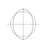
Here are the front and side contrours of the horn. The narrowing of the throat is very subtle.
I don't claim to have found the holy grail of horns, it's just my attempt to tackle the problem.


What's the main difference between a traditional diffraction slot, or, as Dr. Geddes just noted: slit, and a smooth/soft diffraction slot?
A traditional diff. slot features a constriction > there is only expansion in one plane - the vertical in most cases, and a narrowing in the other.
As a result, the wavefront suddenly widens as soon as it reaches the end of the slot, with all the dire consequences.
A soft slot omits the narrowing.
A traditional diff. slot features a constriction > there is only expansion in one plane - the vertical in most cases, and a narrowing in the other.
As a result, the wavefront suddenly widens as soon as it reaches the end of the slot, with all the dire consequences.
A soft slot omits the narrowing.
Last edited:
I can't remember the exact expression that I used, but it actually doesn't narrow down. Just expands the horizontal and pretty much keeps the vertical at 7 degrees (which is the exit angle of the BMS 4550)
This is what I get for an axisymmetric shape. The throat impedance is indeed increased below 1 kHz by the means of the resonance. Is this a good idea? Maybe, I don't know.
Now the question is whether and how much can an elliptical shape improve this. Maybe it can.
Right now there is this waveguide being made (422 x 364 mm; 1,4" throat for 18Sound ND3T) -
Could it be made for a 2" driver?
Also, would you recommend this type of waveguides for coaxial compression driver? I have a pair of B&C DCX50-8's and those have a ring mid-tweeter around a small tweeter (which has its own min-trumpet). I guess the ring mid-tweeter generated a spherical wave so it would go well with a waveguide, and the small tweeter (10K+) would be very directional and therefore beam tightly without reflections on the waveguide's walls. So I see what could make this a good choice - however, I do not foresee what could go wrong...
I can't remember the exact expression that I used, but it actually doesn't narrow down. Just expands the horizontal and pretty much keeps the vertical at 7 degrees (which is the exit angle of the BMS 4550)
This seems to be the best solution in order to keep distortion products to a minimum.
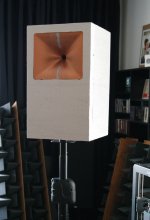
I've made a scaled XPS model (1:2). This can be fun as so much things can be tested without much effort (rounding the edges, etc.).Looks great, are you mounting this on a baffle or freestanding?
Attachments

Last edited:
Obviously, I didn't comprehend the actual inner shape. This is quite different than what I showed. I've tried all different kinds of these "higher loading" variants, it always beamed more than I would like.And in fact a diffraction slot is what I would like to avoid.
Here are the front and side contrours of the horn. The narrowing of the throat is very subtle.
I don't claim to have found the holy grail of horns, it's just my attempt to tackle the problem.
View attachment 924366View attachment 924367
I've made a scaled XPS model (1:2). This can be fun as so much things can be tested without much effort (rounding the edges, etc.).
Little Saturday morning treat!
I also consider trying a cardioid midrange with (dampened) side ports. Tritonia is designed a passive three-way from the start so that naturally suggest itself.
I only don't have an idea how to model the damping material in the scale used.
I only don't have an idea how to model the damping material in the scale used.
- Home
- Loudspeakers
- Multi-Way
- Acoustic Horn Design – The Easy Way (Ath4)