2" is already a little too much, IMHO. I'm also not sure about the coaxial CDs - so far I haven't seen any to my liking. The midrange parts are often very good but the HF seem still lacking. But I have no personal experience with any of them. Maybe it's worth it, I don't know. I chose HF1440 for now.Could it be made for a 2" driver?
Also, would you recommend this type of waveguides for coaxial compression driver? I have a pair of B&C DCX50-8's and those have a ring mid-tweeter around a small tweeter (which has its own min-trumpet). I guess the ring mid-tweeter generated a spherical wave so it would go well with a waveguide, and the small tweeter (10K+) would be very directional and therefore beam tightly without reflections on the waveguide's walls. So I see what could make this a good choice - however, I do not foresee what could go wrong...
I found an old post where I tried that even without the rollback: #2647do you have a sim with Tritonia mouth rollback ?
That looked quite nice but now I'm not sure about its validity and will check that now that I have printed them.
I also consider trying a cardioid midrange with (dampened) side ports. Tritonia is designed a passive three-way from the start so that naturally suggest itself.
I only don't have an idea how to model the damping material in the scale used.
Going to crawl out of the wood work here as I may have something to contribute. I have been interested in pairing a CD horn with a passive cardioid mid/low as well. I came across the same problem of how to simulate the damping material.
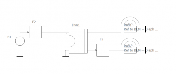
AFAIK, the easiest way to do this is to leverage the LEM aspect of AKABAK. The "Elec-Dyn Driver" has two outputs, one for the front of the driver, and one for the back. You the attach these outputs to two BEM radiator elements, one configured as a front of the driver, one as the back.
The magic however is, now that you have separated front and back of the same driver in LEM, you can independently process the front and back of the driver. Which means, you can low pass just the back wave as if you had put in damping material for the same effect.
Because you now have a back and front BEM element as well, you can also do things like simulate delay or dB loss to dial the ideal settings for achieving a cardioid-like pattern.
I can't confirm if the simulations match real world since its all in software right now, but I have successfully create a super-cardioid simulation using the same logic in the Meyer, Fulcrum, and Dutch patents.
I could also be dead wrong lol 😀
Attachments
Last edited:
I only don't have an idea how to model the damping material in the scale used.
This is the crux of the issues that I had in modeling this idea. You need a very accurate model for the damping including its speed change, which is far more complicated than just looking at damping loss (all of which can vary with frequency.) For this reason I have seen that virtually all attempts at this end up using a "cut and try" approach to get things right. In the D&D case their initial idea was to just use the passive approach, but then some ways down the road they added an active driver. I suspect that they weren't able to get what they wanted passively, which I can certainly understand.
Are there "good" examples of purely passive cardioids?
Well I have the real XPS model (I say "model" because it is in 1:2 scale). I won't simulate it - "cut and try" it what I'm gonna do.
I found an old post where I tried that even without the rollback: #2647
That looked quite nice but now I'm not sure about its validity and will check that now that I have printed them.
Thanks that looks pretty smooth. I'm experimenting with Tritonia variant now, just waiting for my 400x400mm printer. Should have something to show/measure in a week...
Were you able to include the side or rear vents as BEM elements? It was this together with trying to work out a practical way to simulate real materials that caused me to shelve this idea.Because you now have a back and front BEM element as well, you can also do things like simulate delay or dB loss to dial the ideal settings for achieving a cardioid-like pattern.
Would you mind sharing an Akabak project or ABEC script I would like to see what you did 🙂
That's my understanding as well the back subs are designed to leverage close placement to a wall behind them. Not directly part of an active cardioid scheme.I think the D&D (8c) is actually a passive cardioid. The back drivers are just (sub)woofers, as I understand it.
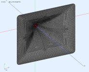
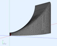
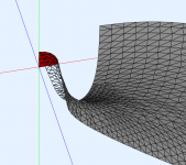
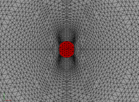
So I noticed that when I generate a horn with ATH and assign the type of simulation to be Freestanding - it still creates subdomains - interior and exterior and the interface in between.
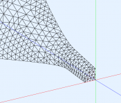
If the horn has a Rollback, the interface happens to intercept both the horn mouth as well as the rollback and back as in the picture.

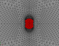
I did a comparison simulating the project as it was and then put all horn elements in 1 external subdomain and removed the interior subdomain and interface.
With 2 subdomains:

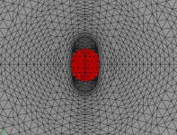
Only Exterior subdomain:

I have only noticed now, and was wondering why doing a rollback almost always made my simulations introduce more ripple.
Wonder if it's me that's doing something wrong, or the interface shouldn't extend through the back...
If the horn has a Rollback, the interface happens to intercept both the horn mouth as well as the rollback and back as in the picture.
I did a comparison simulating the project as it was and then put all horn elements in 1 external subdomain and removed the interior subdomain and interface.
With 2 subdomains:
Only Exterior subdomain:
I have only noticed now, and was wondering why doing a rollback almost always made my simulations introduce more ripple.
Wonder if it's me that's doing something wrong, or the interface shouldn't extend through the back...
See 6.7 (and 6.8.1) in the User Guide. You can adjust the interface(s) or simply disable it altogether (as you did) by "Mesh.SubdomainSlices=".
In the free standing conditions it's probably the most reliable to disable it and use only one exterior subdomain. Sometimes ABEC behaves in mysterious ways, I don't know why.
In the free standing conditions it's probably the most reliable to disable it and use only one exterior subdomain. Sometimes ABEC behaves in mysterious ways, I don't know why.
Last edited:
One more remark - in the CircSym mode don't hesitate to increase the "Mesh.LengthSegments". It doesn't cause solving time rise but can greatly increase the resolution of the mesh.
In terms of AKABAK/ABEC behaving mysteriously - The Interfaces are very picky with normals direction.
It took me ages to do the basic ported enclosure example. I just couldn't see pressure coming out of the port (as one would expect at the cabinet resonance)
Turned out my interfaces (Interior - Port and Port - Exterior) had the wrong direction.
I think that might be that the interface acting as a rigid boundary on it's back side...
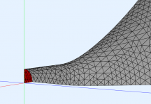
Ok, so I tried disabling it using "Mesh.SubdomainSlices=0"
It still creates 2 subdomain and an interface.
This time the interface is located at the origin and has the same size as the source.

After editing the solving.txt file and manually deleting the subomain and interface it becomes "pretty" again.


My bad! Using
"Mesh.SubdomainSlices=" instead of "Mesh.SubdomainSlices=0" fixes it 😀
It took me ages to do the basic ported enclosure example. I just couldn't see pressure coming out of the port (as one would expect at the cabinet resonance)
Turned out my interfaces (Interior - Port and Port - Exterior) had the wrong direction.
I think that might be that the interface acting as a rigid boundary on it's back side...
Ok, so I tried disabling it using "Mesh.SubdomainSlices=0"
It still creates 2 subdomain and an interface.
This time the interface is located at the origin and has the same size as the source.
After editing the solving.txt file and manually deleting the subomain and interface it becomes "pretty" again.
My bad! Using
"Mesh.SubdomainSlices=" instead of "Mesh.SubdomainSlices=0" fixes it 😀
Last edited:
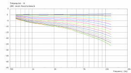
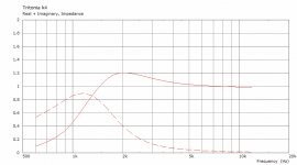
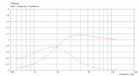
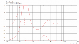
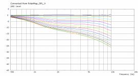
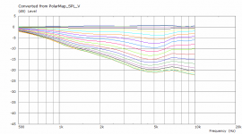
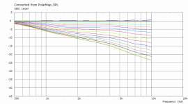
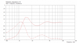
BTW, I tried to increase the 'k' parameter on the Tritonia waveguide -
This is the original (k=1) throat impedance and horizontal polars (10 deg normalized, 0-90/5) in infinite baffle:


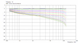
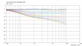
This is for k=4:


This is about what to expect when increasing the loading (still only a bit).
This is the original (k=1) throat impedance and horizontal polars (10 deg normalized, 0-90/5) in infinite baffle:
This is for k=4:
This is about what to expect when increasing the loading (still only a bit).
Attachments
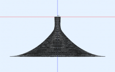
1" throat -> elliptical extension (available soon in Ath 4.7.1):
Throat.Diameter = 25.4
Throat.Angle = -5 + 15*sin(p)^2
Throat.Ext.Angle = -5 + 15*sin(p)^2
Throat.Ext.Length = 40
Throat.Diameter = 25.4
Throat.Angle = -5 + 15*sin(p)^2
Throat.Ext.Angle = -5 + 15*sin(p)^2
Throat.Ext.Length = 40
Attachments
Beta version of Ath 4.7.1, including a demo: https://at-horns.eu/release/elthroat+Ath-4.7.1beta.zip
Attachments
After changing to a 64-bit installation of wine I get:
Jo-Mac-Pro:Ath MacPro$ ls
Horns ath.cfg ath.exe demos doc lib misc
JoMac-Pro:Ath MacPro$
./ath.exe /Volumes/Home/Users/MacPro/Applications/Ath/demos/demo1.cfg
Jo-Mac-Pro:Ath MacPro$
No errors but nothing in "Horns".
Under wine and Mac OS, what should
OutputRootDir =
in ath.cfg be set to? C: or Z: or...
//
Thinking about HOMs & eventually listening to them.
Imagine a stretched string, with its harmonic modes. How much sound does it emit on resonance? First, it needs to be plucked in the right place to excite a given mode, then that mode sounds. The situation in a waveguide driven by a compression driver is different, at least the way I think about it.
What determines how much sound comes from resonances (HOMs) within a waveguide?
The shape of the waveguide, including its terminations, sets up the spectrum of higher order modes - as Dr Geddes' analysis shows. That's like the modes of the stretched string - they exist whether or not they are driven.
But, how much sound do those emit when driven from the throat? Lets assume plane-wave excitation with white/pink noise so that all modes can be excited.
How loudly does a mode sound? That depends on how much sound is diffracted into that mode - also determined by the shape of the waveguide.
All waveguides, even well-terminated OS waveguides, have a spectrum of HOMs.
Adding a region of more rapid curvature, changes the HOM spectrum but, at least as importantly for subtle changes in shape, increases diffraction which scatters sound into HOMS so that they get louder. The effect is strongest for deviations from OS near the throat.
A problem with this is that it is not easy to tell if this will cause audible problems by looking at linear models (frequency responses, etc.).
I found out almost a decade ago that I can't stand listening to some well-known softly-rounded diffraction horns in comparison with a similar size waveguide in GedLee Harper speakers (with or without their foam plugs).
The defects of a diffraction horn might not be immediately obvious without a comparison, but once they are heard, they are hard to forget, and become a big distraction, at least for me.
Ken
And if as a string, it has a decay before the resonance stops. So in order to analyze the HOMs, one needs to introduce time into the equation. The worst stuff come "afterwards"...
//
//
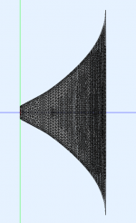
...more open vertically -
Throat.Diameter = 25.4
Throat.Angle = -2 + 30*sin(p)^4
Throat.Ext.Angle = -2 + 30*sin(p)^4
Throat.Ext.Length = 40
Throat.Ext.Included = 1
Throat.Diameter = 25.4
Throat.Angle = -2 + 30*sin(p)^4
Throat.Ext.Angle = -2 + 30*sin(p)^4
Throat.Ext.Length = 40
Throat.Ext.Included = 1
Attachments
- Home
- Loudspeakers
- Multi-Way
- Acoustic Horn Design – The Easy Way (Ath4)