did anyone of you tried to generate a midrange horn contour with ath4?
I already asked here but there was no feedback. Does this mean nobody tried or does this mean ath4 is not designed doing this?
Acoustic Horn Design – The Easy Way (Ath4)
I already asked here but there was no feedback. Does this mean nobody tried or does this mean ath4 is not designed doing this?
Acoustic Horn Design – The Easy Way (Ath4)
I'm working on that - making excess group delay part of the standard report.
You can do this easily with REW; import impulse response in REW -> make minimum phase version -> subtract this from original
It's mainly the size alone that determines directivity in this range. Don't expect details such as the throat angle to make much difference. Why don't you just try something and see where does it lead you... I do this all the time.when trying to model a midrange waveguide for example an 6,5 inch midrange cone driver how you would start configuring the config file?
Normally this driver then runs between the 200-3000Hz range.
In this frequency range the (especiall at 200-1000Hz) driver naturally has a wide dispertion pattern. So does this make sence to adjust the "Throat.Angle" to mach the directivity in the lower starting range? So for example set this to about 50 degrees which will maybe match the 200-1000Hz range (-6db; in both directions)? How you would start the config file (indpenenent form coverage angel or which contour to use) modelling a midrange with ath4?
That's still a lot of work 🙂
Well, depends on your definition...
The advantage; you can compare it with your real measurements, I tried to extract excess phase properties from abec in the past and I have to say that I am not too confident about the capabillity of abec/ bem in general to get all featurws inuded.
I dont have any proof for this, but only rememberthat I did not get correc f result when trying to simulate a room at higher freuencies ( yes the grid size was fine enough)
A Brep surface made from a mesh will have too many facets, you have more luck trying to thicken a regular surface. Can you create that guide using Grid Export or is it an STL you got from somewhere?
The only option I found if you only have a mesh is to use the Brep surface to cut a solid block then use solid modelling tools on the block to make the back however you want it.
I attached a guide describing what I did in this post before mabat released the Fusion scripts.
Acoustic Horn Design – The Easy Way (Ath4)
You need to create ("loft") the surface from splines imported via the Add-ins included in the Ath package. It doesn't work with STLs, I suppose.
This may be tricky sometimes.
Thanks, playing with ATH grid exported slices and profiles with Fluid's guide, see if I can figure it out...
In Fusion this is done via the "Ath4_SurfaceImport" add-in (open the exported slices). Or you can import only the slices by "Ath4_CurvesImport" and create the surface by the loft feature manually afterwards, which may be the more robust way how to do it. It's a long time since I did this.
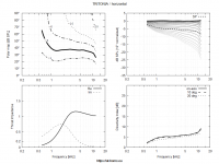
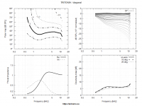
BTW, the reporting functionality so far assumes axial symmetry. Here are reports for the Tritonia waveguide, H, V and D planes separately (as if it was axisymmetric), half-space. Now I have to implement such report for a general non-axisymmetrc shape, composing the calculation of the total radiated sound power of more points on the (hemi)sphere - the more dense the spatial sampling the better.
Attachments

You can do this easily with REW; import impulse response in REW -> make minimum phase version -> subtract this from original
This is not excess group delay, it's the non-minimum-phase. Even the minimum phase portion will have excess group delay.
Group delay is the rate of change of the phase with frequency. Excess group delay takes out the constant phase delay due to propagation time.
Isn't the propagation time irrelevant? It will shift the whole (excess) group delay curve up and down along the time/delay axis but isn't it the non-flatness of the curve we are interested in here? We can also assume that any propagation time delay is compensated even before any further analysis - this will definitely be the case.
Last edited:
Isn't the propagation time irrelevant?
Yes, exactly, that's why we take it out, leaving the "excess" group delay, which is all what I said.
It makes no sense to me then. I understand that we take the minimum phase group delay, the actually simulated group delay and the excess group delay is the difference between the two. Whatever propagation time delay there is - that's just an additive constant, if any.
Edit: OK, maybe I see what you mean now.
- In ABEC there's a possibility to compensate the calculated farfield phase for the propagation delay automatically, relative to the origin of the rotation, so there should be no propagation delay to start with. I haven't checked that yet. We can always do this easily for any known distance from the source.
Last edited:
Your looking to flatten the phase as much as possible before you find the group delay. This is arbitrary of course as the "flattest" is subjective, but in either case the group delay will be a value of how much it differs from a pure delay. Some will be negative and some positive, but the magnitudes will be constant. This might show something and it might not. It's a hypothesis that I had that might show some subjective effects that cannot be seen from a frequency response alone. This is what research is all about - trying tings and having some of them work out. We never hear about the ones that don't (like my trying to find thermal modulations in drivers.)
How would you recognize it actually shows something? I mean, some excess group delay is almost a natural attribute of all common crossovers, yet they present hardly any audible problem... Don't they?... This might show something and it might not. It's a hypothesis that I had that might show some subjective effects that cannot be seen from a frequency response alone. This is what research is all about - trying tings and having some of them work out.
- How would it have to look like?
Last edited:
In Fusion this is done via the "Ath4_SurfaceImport" add-in (open the exported slices). Or you can import only the slices by "Ath4_CurvesImport" and create the surface by the loft feature manually afterwards, which may be the more robust way how to do it. It's a long time since I did this.
Still scratching my head on this one.
Which is best to work on profile or slices?
I've imported into fusion and tried lofting, no luck yet...
Just want to loft then thicken. cant figure it out. spent a day on it figuring it out lol
Attachments
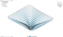
The script Marcel made does it automatically and you end up with a body.
I personally make a solid object aligned with the mouth and use the "shell" body to cut the solid object into two.
Then work the back to make the object printable 🙂
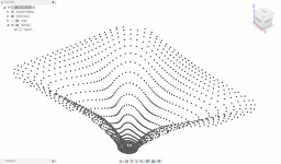
You can also manually loft between every horizontal slice. (The second picture)
I personally make a solid object aligned with the mouth and use the "shell" body to cut the solid object into two.
Then work the back to make the object printable 🙂
You can also manually loft between every horizontal slice. (The second picture)
How would you recognize it actually shows something? I mean, some excess group delay is almost a natural attribute of all common crossovers, yet they present hardly any audible problem... Don't they?
- How would it have to look like?
Well, when I "flatten" the phase curve of my loudspeaker system then there is only about 60 degrees of phase change across the audible band. Not much to be sure even though it is quite uncommon. But then I was thinking that maybe it's not just the phase change over a large bandwidth, but the rate of change with frequency, which is the group delay.
It is well known, you can look this up in (Brian Moore's AES paper on perception of group delay) that it's perception rises with rising SPL. This implies that large local group delays may be more audible with level than smoother ones. I believe that this is a large part of "horn honk" that I think that we have all heard - it's perception increases with level until it sounds like nonlinear distortion - which it is not.
- Home
- Loudspeakers
- Multi-Way
- Acoustic Horn Design – The Easy Way (Ath4)