since you haven't had many bites ...
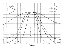
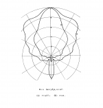
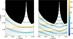
The first (left, more constant coverage) one.
If I was much younger and wasn't happy with the response much above 10kHz, I'd switch to a smaller driver.
At any age, I'd want a way to extend the constant coverage response to even lower frequencies, by way of a larger waveguide or incorporation into an array.
Ken
I am trying to achive a wide horizontal coverage for an 33mm driver and just playing around with differnt settings in ath4. Independent from the settings which one of those two coverage version is to prefer?
The first (left, more constant coverage) one.
If I was much younger and wasn't happy with the response much above 10kHz, I'd switch to a smaller driver.
At any age, I'd want a way to extend the constant coverage response to even lower frequencies, by way of a larger waveguide or incorporation into an array.
Ken
I would also want to extend the band radiated by the waveguide as low as feasible and that typically means a bigger driver. Then you have to decide whether to choose the sudden drop in beamwidth just above 10 kHz (for a 1.4" throat) or let the DI rise more smoothly from lower frequencies (together with somewhat better loading *). I'm still not sure what's better.
* In case of an OS-SE profile this is easily accomplished by modifying the parameter 'k' ("throat expansion factor").
* In case of an OS-SE profile this is easily accomplished by modifying the parameter 'k' ("throat expansion factor").
Last edited:
People still prefer "the worse" until more freestanding waveguides are built and evaluated 🙂
Now, it's difficult to blame people for that because our rooms, halls, theatres, cars, buildings, streets are all rectangular. Only the speakers and their diaphragms / cones are circular. This is also why you're a considered an "out of the ordinary" fellow if you have a circular / spherical office whereas your mate who has a rectangular one is not.
From what I gather from the shape and approach seen in the JBL image control waveguide and the various comments / discussions on the internet, the shape of its target coverage area appears to be rectangular, just like everything else. After all some of the white circular waveguides look like the toilets in men's rooms.
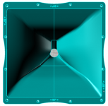
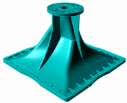
JBL M2 for The Poors
Last edited:
Then you have to decide whether to choose the sudden drop in beamwidth just above 10 kHz (for a 1.4" throat) or let the DI rise more smoothly from lower frequencies (together with somewhat better loading *). I'm still not sure what's better.
That probably depends on the intended use or simply preference since the direct sound field dominates at these frequencies. I think the latter makes sense if you wish to significantly toe in your speakers or cover multiple listening positions. But if one tends to listen more on axis it maybe makes more sense to optimize the beamwidth for well behaved reflections in the area they matter the most (i.e. below 10k).
Newvirus2008: Totally, at some point the aesthetics must be considered and you decide whats best for your project. It is potentially better sound in a smaller package with the round freestanding version and there is nothing wrong to exchange some of that for better visual appeal.
Acoustic Horn Design – The Easy Way (Ath4)
@Ro808 - Thanks. If I understand your question correctly: no, most of the energy leaves the mouth, so if a HOM is excited deep in the horn, the effect reaches the listener. I feel I might be misunderstanding your point.
You seem to be knowledgeable and you're probably familiar with the research that has been done on the subject.
As B. Kolbrek puts it:
"Higher order modes describes the deviation from simple wave propagation in horns and sound fields in general. If the wave front in the horn is not plane, cylindrical or spherical, it can be described as a sum of mode functions. In one of my earlier blog posts, and also in the reports available under Horn Theory, I have discussed this in some more detail.
Since it appears that many believe that the existence of higher order modes in horns (often just called HOM) is a quite recent discovery."
Obviously, it's not. Kôzi Satô was the first to study the sound field of a conical horn as an expansion in spherical harmonics (modes in spherical coordinates) in 1929 (see attachments).
Makarski's "Tools for the Professional Development of Horn Loudspeakers" is probably the most comprehensive on the topic, according to Kolbrek.
Not hindered by a great lack of knowledge of fundamental physics, I have read all the studies mentioned by Kolbrek, and (many) more.
The problem with HOMs is their "nature": evanescent, frequency/pressure dependent, unavoidable etc., which not only makes them hard to quantify/model/predict, but - even more importantly, also makes it difficult to actually measure them, trace the sources and relate the results to observable (disruptive) phenomena.
In a recent study, Dong et al. concluded:
"Although the range of 8 to 16 kHz still falls into the design band and is below the cut-on frequency of the first axisymmetric higher-order mode of the waveguide (16:62 kHz), application of the measurement method in this range yielded a sudden increased reflection coefficient in a level much higher than in 2–8 kHz, which implies the propagation of the non-axisymmetric modes in the waveguide and the measurement method was therefore invalid. This may be caused by the defect of axisymmetry of the waveguide-horn system and excitation of non-axisymmetric modes by the compression driver."
Attachments
Last edited:
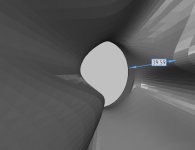
Regarding propagation of higher order modes in- and outside the (in this case exponential) horn:
"While an incident plane wave will excite higher order modes within the horn, these propagate towards the throat until the decreasing diameter raises the cutoff frequency and energy rejoins the fundamental mode."
Phase contours of the scattered pressure (degrees) in response to an on-axis source at 10.6 kHz (left panel) and 17.7 kHz (right panel):
Attachments
Last edited:
That's the same question as "If the sound reinforcement systems sounded bad, would anyone use them?"If HOMs caused by strictures / slots were unacceptable, would Makarski design such a horn?
- But you seem to hint that the answer is no. Why would you think so?
Last edited:
It's more of a matter of historically charged public opinion and misconceptions about modern horn technology, its implementation versus the variation in product quality of commercial Pro Audio.
A well-known example of a brand that predominantly makes good sounding speakers is RCF (including EAW), a lesser known name is Seeburg Acoustic Line.
A well-known example of a brand that predominantly makes good sounding speakers is RCF (including EAW), a lesser known name is Seeburg Acoustic Line.
Last edited:
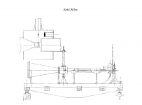
M2 clone - just got there
Managed to obtain the W20" x H18" x D4.5" dimensions. My parameters were
Throat.dimension = 38
Coverage.angle = 60
Depth = 108
Guide.curve.width = 68
Guide.curve.Distance = 0.5
Throat.extension = 6
Expand.rate = 1.5
The above results in a 40mm position for the knuckles that has been confirmed by sebackman on audioheritage.
Compact monitor - Page 7
Although the M2 horn looks slightly chubbier than the ATH clones (from photographs), the latter method is nevertheless very close, thanks to Mr Marcel (mabat) for sharing such a nice piece of computer software. The guide curve concept may also be used to approximate other curved wall waveguides besides that of the M2, such as the 2374 / 84, PTs, CMCD midhorns etc.
Apologies for the lack of graphs as I have a little CPU that wouldn't survive calculations (thermally).
Attachments
Last edited:
Newvirus2008 (you were at least 11 years ahead of the current and most likely the future situation, with your forum name 😀), nice work!
Looking forward to the sims.
...On to the next stage in the "cloning process" 😉
Looking forward to the sims.
...On to the next stage in the "cloning process" 😉
Attachments
Last edited:
"A matter of personal preference", I guess.Why is the waveguide not flush with the body? 😕
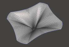
I got the same effect of clipped corners when I tried to make a more highly asymmetric waveguide recently when someone was asking for one.I've just realized the morph feature doesn't work properly in 4.7 for some reason. I'll look at that, it is a long time since I tried this.
- Home
- Loudspeakers
- Multi-Way
- Acoustic Horn Design – The Easy Way (Ath4)