It could show any signal not "in time", compared to the corresponding minimum phase system. If it's flat it means the system is actually minimum phase. Which seems to be the case for the device just measured.
Now it would be useful to measure something really "bad".
Or maybe this is still too coarse measurement, I don't know.
Now it would be useful to measure something really "bad".
Or maybe this is still too coarse measurement, I don't know.
Last edited:
The first two are what I would expect, where the constant delay has been taken out of #2, i.e. the curve shifts up and down, so plot 2 is precisely what I was looking for. I have no idea what plot 3 is, unless it has taken out the non-minimum phase.
I'm betting that a poorer design would look much worse.
I'm betting that a poorer design would look much worse.
But wait, the sun is round, so does that change anything?
Yes Sir, the sun definitely is round, at least for all practical intends and purposes, it is. However, I was referring to how common it is for man-made listening areas to be rectangular, citing some very common examples. It is also worth noting how most of our speaker enclosures have rectangular profiles while the speakers themselves do not.
I think Patrick Bateman's post in "JBL M2 for The Poors" has already made this point regarding the JBL "image controlled" waveguides. I was just saying that it is a normal tendency for us to ditch the circle, which even JBL seems to acknowledge. No pun intended.
In the past I came to similar conclusions, especially wrt to the 2352. The M2's main benefits (and design objectives) are related to the wide coverage angles and smooth off-axis response.
Yes, the 2352 is inferior in the vertical department. However, I really don't feel that it could be a big problem considering the small listening areas that monitors are meant to be used in.
I just felt that the M2 horn could have been slightly deeper, in order to be able to accommodate the bigger 1.5" drivers to comfortably play at 500Hz or thereabouts. After all, it is still diffraction-based isn't it ?
What do you mean by plot 3? The plots are labeled in their headers. Am I missing something?I have no idea what plot 3 is, unless it has taken out the non-minimum phase.
Width of guide curve
Mr. Marcel,
ATH doesn't complile when my guide curve width is lesser than the throat diameter. What if I wanted to get the shape first and then make the throat bore through the middle of the horn ? Is it possible in any way ? Thanks.
Mr. Marcel,
ATH doesn't complile when my guide curve width is lesser than the throat diameter. What if I wanted to get the shape first and then make the throat bore through the middle of the horn ? Is it possible in any way ? Thanks.
I'm not sure I follow. Guide curve smaller than the throat outline would lead to a negative coverage angle which is not allowed.
Maybe you could try to use the explicit expressions instead (parameters as functions of 'p'), which offers by far greater freedom in overall design. The guiding curve is only an aid for those who want it quick and simple...
- You could also experiment with negative throat angle(s), but whether it can be combined with a guide curve smaller than the throat I'm not sure.
Last edited:
GD looks to be very low and linear. Why not also show a waterfall. Phase/GD is still the timing aspect of the "first" energy/cycles coming out if the speaker. What comes after, albeit less in level, is also interesting.
//
//
Well the phase and the GD are directly tied to the magnitude response in this case - we can calculate the phase/GD from the magnitude response alone, i.e. the system is minimum phase - there's no new information in phase response in this particular case, certainly not is the resolution of the measurement.
Which also means that if we EQed the magnitude response flat with a minimum phase filter, the phase response would be also flat, group delay zero and a waterfall perfectly clean.
Which also means that if we EQed the magnitude response flat with a minimum phase filter, the phase response would be also flat, group delay zero and a waterfall perfectly clean.
Last edited:
Guide curve smaller than the throat outline would lead to a negative coverage angle which is not allowed.
Maybe you could try to use the explicit expressions instead (parameters as functions of 'p'), which offers by far greater freedom in overall design.
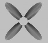
I do not mean a negative coverage angle but the horn becoming like a pipe (clipped at throat diameter), like in the picture below.
Yes, the superellipse formula could be written however, I get NaN errors whenever the throat is bigger than the curve. So I don' think it would be any different from what it is now.
One option I see is to make the horn with a smaller throat and then obtain the larger throat using CAD. Then maybe import the CAD into ABEC, solve and verify. Complicated.
Thanks anyway.
Attachments
Last edited:
I don't really understand what are you trying to do but a pipe can be added to any shape by using Throat.Ext.Length and Throat.Ext.Angle.
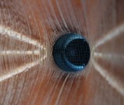
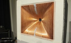
Impressive!
Is this manufacured with a «standard» 3d-printer?
Best regards
Gisle
Is this manufacured with a «standard» 3d-printer?
Best regards
Gisle
Last edited:
Yes, a cheap printer (Anycubic i3 Mega S) but it serves the experiment well. I'm yet learning the stuff along the way.
Anycubic Chiron was delivered today - I'll be able to print it in the real scale on that one, both halves in one go 🙂
Anycubic Chiron was delivered today - I'll be able to print it in the real scale on that one, both halves in one go 🙂
Attachments
Last edited:
This is a very nice down to earth explanation of minimum phase.
Minimum Phase
What more information does one find in the Group Delay Curve as opposed to the Phase Curve?
And btw what windowing did you use?
Minimum Phase
What more information does one find in the Group Delay Curve as opposed to the Phase Curve?
And btw what windowing did you use?
The definition of "excess phase" in that article is different than the one that I am using, hence some confusion. To my knowledge there is no dictionary definition so I suppose that different definitions are possible. If anyone knows of a "dictionary" definition then please let me know as I will then need to change my terminology. Although I don't know what else to call it.
I am talking about the group delay (GD) that has the time-of-travel delay removed - which is irrelevant. When you see group delay curves with negative values then you know that some travel time has at least been partially removed. If the +- areas are about equal then the travel time has been maximally removed.
The "excess phase" in that article is the difference between the minimum phase group delay and the actual group delay - very different things.
My hypothesis is that the integration of my "excess GD" magnitude squared could be a strong indication of perception. Many things will affect this, but problems in a waveguide may not be wholly correctable with EQ as they can be in other situations. This could make for a Figure of Merit for a design along with frequency and power responses.
Last edited:
OK, now I see the cause of the confusion. My "plot #3" shows exactly the difference between the minimum phase GD and the actual GD. If this is flat, the system is minimum phase. The problem may be that the extraction of the minimum phase from the measured data is not very straightforward and some phase error is to be expected - this is most probably what causes the deviation from flat line towards the bandwidth edges.
For a minimum phase system the phase and the GD is completely correctable with EQ, along with the magnitude response. So in that case there's nothing to be worried about.
For a minimum phase system the phase and the GD is completely correctable with EQ, along with the magnitude response. So in that case there's nothing to be worried about.
That is not, in general true. Many speakers have non-minimum phase characteristics. The example that you showed may not, but again, that is true only at one point in space - the measurement point and not necessarily true throughout the sound field.
It is My Excess Group Delay (MEGD) that I am interested in, not the one in your plot 3. Your plot 2 shows significant MEGD and the attached article did show some serious problems as well. Maybe it is correctable, in which case it should be, but in the end it is the total system that matters, not any individual driver.
I looked in Digital Signal Processing by Alan Oppenheim and while minimum phase and nonminimum phase is widely discussed, no mention is made of "excess group delay", So this seems not to have a standardized definition.
Last edited:
- Home
- Loudspeakers
- Multi-Way
- Acoustic Horn Design – The Easy Way (Ath4)