I assume it could. It's a polar map for the interior of a infinite OS waveguide (or close to that). What influence it has on a far field performance of a finite horn is still to be found out. That takes another simulation.
Step-tapered throat amplitude, 2" throat, 75 deg coverage (left: flat; right: four steps from the axis: 1 - 0.9 - 0.8 - 0.75):
This throat shading has to be done by the phase plug, which is were my patent comes from. In it I show how the phase plug can be designed such that amplitude shading would occur at the throat. I never actually made drivers, so I could never try it. Maybe today with 3D printing it's a piece of cake, back then nothing like that existed (for reasonable amounts of money.)
Dave, could you recommend a book describing the math of the evanescent wave effect ? To me it is not evident the nature of the effect in acoustics.
Hi Dmitriy
The animation that Marcel linked is pretty nice as a starter, thanks Marcel.
The standard book for this aspect seems to be "Fourier Acoustics" by E. Williams.
I must admit I haven't had the chance to read it much yet so I don't know how it compares other classic works like P.M. Morse on this subject.
Morse would be the other place I would start.
Best wishes
Your in luck!
Thanks, I will study it this afternoon.
I think your comments essentially reflect my concerns.
My first impression is that the measurements will be insensitive to the different modes, except in the evanescent wave area close to the throat.
So the data we want will be contained in relatively small differences between measurements, in comparison to the size of the measurements themselves.
That will be mathematically evident as a near-singular matrix, just as you observed.
You wrote that the work was curtailed at B&C, how far did it actually proceed?
You worked out the maths, was there a prototype built, tested?
What approximate mic distances did you have in mind (or test if it went that far)?
Is there any test data or estimates of what sort of accuracy would be needed?
I have a lathe and mill - a PWT is a project I have considered, could actually build in less than a human lifetime.
Would need a pressure mic...hmmm
Best wishes
David
I think your comments essentially reflect my concerns.
My first impression is that the measurements will be insensitive to the different modes, except in the evanescent wave area close to the throat.
So the data we want will be contained in relatively small differences between measurements, in comparison to the size of the measurements themselves.
That will be mathematically evident as a near-singular matrix, just as you observed.
You wrote that the work was curtailed at B&C, how far did it actually proceed?
You worked out the maths, was there a prototype built, tested?
What approximate mic distances did you have in mind (or test if it went that far)?
Is there any test data or estimates of what sort of accuracy would be needed?
Best wishes
David
My role at B&C was to lay down the theoretical foundations of projects that they would move forward. We did several and some of them were published. But I left just as I delivered the document that I attached. I do not know what, if any, steps were taken to proceed with this project.
B&C had done some testing that indicated that the wavefront from the drivers was certainly not flat, but their procedure was limited and could not differentiate the different modes. My approach could.
As to the evanescent waves, please remember that this is only an issue at LFs, and that HOMs are not at issue at these frequencies. So in the region where HOMs are a concern, there are not evanescent waves because at those frequencies they propagate. This does mean that the wave shape at LFs may be hard to obtain, but that's because only the plane wave will propagate anyways, making it a non-issue as far as what reaches the listener. Wavefront curvature is primarily an issue when the HOMs can actually propagate to the mouth, and if they can do that then measuring them is not a problem.
As to the mic spacing, I would think that a regular spacing would not be good, or at least not what I would try at first. But, the mathematics should be able to handle any spacing as the singularities that would occur with a regular spacing would just get resolved by the SVD calculations.
Evanescent waves in a tube is not discussed in any of the texts books by Morse or Williams. Williams book has a small section on them, but not as they apply to our situation. One can see they mathematically by looking at the PDF that I linked. If Kr > K then Kz become imaginary and the normal complex exponential defining wave propagation becomes an exponential decay with Z.
Hi Dmitriy
The animation that Marcel linked is pretty nice as a starter, thanks Marcel.
The standard book for this aspect seems to be "Fourier Acoustics" by E. Williams.
I must admit I haven't had the chance to read it much yet so I don't know how it compares other classic works like P.M. Morse on this subject.
Morse would be the other place I would start.
Best wishes
Thank you, Dave.
In addition to the E.Williams book I have found discussion on the evanescent waves in "An Introduction to Acoustics" by S.W. Rienstra & A. Hirschberg.
sorry for sullying the thread with my inane questions...do evanescent waves decay exponentially?
Not yet. BTW, a great thing about this formula is that the exact shape and size of the mouth (whatever that may be) can be defined directly.Is this gold
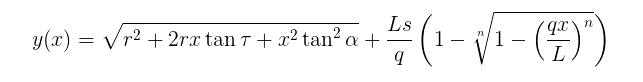
already implemented in ath4?
I may not have ever stated this directly, so I will do so now.
I see no good reason to use a square/rectangular mouth as is so often done. The mouth area is of no relevance, so making it larger does nothing. (for a given shape a larger mouth is a benefit, but changing shape to add area is not.) The optimal shape is clearly an ellipse with a circle being the most straight forward to fabricate. A rectangle also has a failing directivity along its diagonals, an ellipse won't. So why anyone would make a waveguide rectangular is simply beyond my understanding. All the benefits are with the ellipse and all the detriments with the rectangle.
I see no good reason to use a square/rectangular mouth as is so often done. The mouth area is of no relevance, so making it larger does nothing. (for a given shape a larger mouth is a benefit, but changing shape to add area is not.) The optimal shape is clearly an ellipse with a circle being the most straight forward to fabricate. A rectangle also has a failing directivity along its diagonals, an ellipse won't. So why anyone would make a waveguide rectangular is simply beyond my understanding. All the benefits are with the ellipse and all the detriments with the rectangle.
I see a practical drawback with an ellipse - it must grow in width compared to a circular mouth, if the vertical directivity is to be kept controlled down to a crossover frequency. I see a "squarish" superellipse as a better choice in practice - you can see the diagonal polars simulated here (in the post below the linked one): Acoustic Horn Design – The Easy Way (Ath4)
It still looks quite good to me. The radiation pattern overall may be in fact closer to that of the woofer. Isn't that a good thing?
It still looks quite good to me. The radiation pattern overall may be in fact closer to that of the woofer. Isn't that a good thing?
Last edited:
How could something not round be closer to the directivity of something that is round?
The width problem is correct, but maintaining the width of the ellipse will still have excellent horizontal control, but the vertical will be a little bit worse because of the narrower height. One could make the flar go out father on the vertical to the same height and width and this would not have these problems.
I built and tested a waveguide almost exactly like what you show. The corners were squared off as they progressed to the mouth. My results were disappointing as some things improved while others got worse. I think that I mentioned this before.
Closer to a round woofer, compared to an ellipse, that is.How could something not round be closer to the directivity of something that is round?
That would be an interesting option. I could make this easily happen within the software.One could make the flar go out father on the vertical to the same height and width and this would not have these problems.
Last edited:
Closer to a round woofer, compared to an ellipse, that is.
Well then you are not talking about different V vs, H directivity, as that will always have a mismatch from woofer to tweeter. One of the reasons that I stuck with round.
That's right. I agree that as the axial issues go away (which they do if done right), there's no reason not using round. I'm closing the loop to round waveguides as well - what I started as a quest for a better shape leads me back to where it started. "Only" with much improved axial performance than before - that was part of the quest.
... One could make the flar go out father on the vertical to the same height and width and this would not have these problems.,,
A better option is to project the ellipse on the surface of a sphere:
A Normalized Stereographic Projection for Spherical Horns – Sphericalhorns
- Home
- Loudspeakers
- Multi-Way
- Acoustic Horn Design – The Easy Way (Ath4)