Here's the ST260W even wider - the old trick of rotating the profile.

Code:
R-OSSE = {        ; ST260Wr3
  R = 130
  a = 50
  a0 = 8
  b = 0.38
  k = 1.8
  m = 0.72
  q = 3.20
  r = 0.26
  r0 = 12.7
  tmax = 1.1
}
Rot = 7To the cost of a sharper beam upwards...which means more movement/jumping of fixed sound sources in the recording when moving head sideways.Of course it is, see the ST280E: https://www.diyaudio.com/community/...-design-the-easy-way-ath4.338806/post-6760695
//
Anyone have their rule of thumbs set for the audibility of this beaming in practical situation?
Quick estimation for 2.5m listening distance 10 degree movement is about 40cm or so which is already past 1ms in delay and precedence effect shifts the image anyway. If speakers are pointed to middle of three person sofa about 15-20 deg to either side is enough to cover the whole sofa, of course more if toed in for time/intensity trading. Basically this means that if (VituixCAD) listening window is within 1db from design axis then it should cover the sofa just fine.
I've noticed I always gravitate towards on-axis when trying to critically listen, and thats with ST260. Perhaps its the settings I'm having (bit drooping highs or something) or the CD I'm having, perhaps there is many effects (like Griesingers proximity) or just the "increasing brightness" that draws me towards on-axis. I've got the speakers little bit toed-in front of me on practical listening postion (sofa) for some time/intensity trading.
Gentle smooth slope on system DI seems to make the sound about the same anywhere on the room and its only critical listening that draws me to certain spot in the setup. On our living room and with asymmetric (practical) positioning the ST260 has perhaps too narrow coverage as there is not enough envelopment until quite close to speakers, which is not necessarily a bad thing and my point is envelopment would be about the same even if the waveguide was beaming some.
On this basis I'm open for little bit of beaming as long as the DI slopes gently and sofa gets roughly same response I'd be happy, no dramatic difference. But this is something to be tested whats too much and whats too little.
I've got sth100 tractrix horn that got some beaming to it, wasn't bad but its some time I listened to it and should revisit it but its another crossover and all so perhaps if there is long sick leave or something, extra time 🙂
Last edited:
With my ST260 I experience quite some shifting in the stereo soundscape at times. A voice can move almost half width of the soundscape. I have turned off the LF in my 2-ways and it remains while with LF only, its mostly gone so it seems to be tied to the WG. Xo at 1,7. No toe-in. 2m between speakers, 3m to sofa. Interesting is that I find it can really be up to the recording - some beam a lot, some don't. So not only the speakers apparently...
//
//
^ try toe in, should make image more stable. Now when the speakers are toed out from you and if your head moves both time and intensity favors the closer speaker and image moves quick to that side, perhaps collapses the whole image to that speaker. If they are toed in to cross in front of you and coverage angle is relatively narrow intensity changes opposite to time and the result is more stable image, time and intensity working against each other resisting the image collapsing to closest speaker.
As intensity is about the same within listening window on ST260 (at least in my ~2.5m equilteral triangle and toe-in) so only time changes when head moves, and image shifts with head. But, the image is stable, its just changes position with head and stays front of you between speakers.
Downside from the toe-in is that the envelopment/spaciousness stuff might change depending on your room and acoustics so its a trade-off unless you can do what ever you want with the room, position speakers and listening spot, manipulate acoustics and so on. On a too dry living room you could additional set of speakers to bring in some envelopment/spaciousness if you wish 😉 Or center channel to really stabilize the image.
Last edited:
It is nice though what one can achieve with tmax > 1. Here is an example:
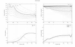
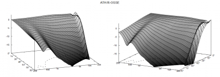
Is the bump low enough to be attenuated by the crossover filter?
Code:
R-OSSE = {
  R = 225
  a0 = 15.5
  a = 30
  r0 = 12.7
  k = 1
  r = 0.423565298249014
  m = 0.721415581088513
  b = 0.258557796245441
  q = 3.63763612927869
  tmax = 1.1862471354194
}

Is the bump low enough to be attenuated by the crossover filter?
With regard to Internal Ring Inserts (R-OSSE rev7 page 27)
I have a B&C DE250 compression driver. Conical duct is 24mm deep. Somewhere between 12 & 14 degree exit angle (my tools aren't accurate enough to measure precisely). Entrance diameter is between 19 and 20mm. Exit diameter is 25mm at plastic conical exit, press fit into a 28mm bore in the metal.
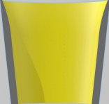
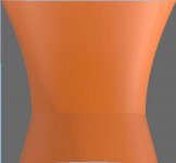
In general, is it better to immediately compress the Entrance diameter down to 16mm and use a ~13.4 degree 16mm long conical duct to a 20mm Exit diameter into a horn with matching angle (Yellow r0 = 10, a0 = 6.7). Or is is better to compress from the existing ~20mm Entrance diameter down to 16mm over a length of 8mm and use a 0 degree matching angle (Orange r0 = 8; a0 = 0)?
Wondering how to approach a ring insert design for Hi-Fi home use.
Attachments
Hi,Here's the ST260W even wider - the old trick of rotating the profile.
Code:R-OSSE = { ; ST260Wr3 R = 130 a = 50 a0 = 8 b = 0.38 k = 1.8 m = 0.72 q = 3.20 r = 0.26 r0 = 12.7 tmax = 1.1 } Rot = 7
View attachment 1125837
HNY!
I had a look (ran my optimizer) at the design you published and came up with that while fixing the first 4 parameters to have a better apple to apple comparison:
Code:
R-OSSE = {
  R     = 130 ; [mm]
  a     = 50 ; [deg]
  r0    = 12.7 ; [mm]
  a0    = 15 ; [deg]
  k     = 3.374 ; []
  r     = 0.2913 ; []
  m     = 0.7126 ; []
  b     = 0.2714 ; []
  q     = 2.754 ; []
  tmax  = 1.073 ; []
         }

  Rot   = -4.095 ; [deg]
Optimized full report
ST260W vs optimized Normalized @00deg Blue/solid = ST260W:
ST260W vs optimized Normalized @10deg Blue/solid = ST260W:
ST260W vs optimized Normalized @00deg Blue/solid = ST260Wr3:
ST260W vs optimized Normalized @10deg Blue/solid = ST260Wr3:
With regards to diffraction, I do believe that normalizing to 00deg and trying to minimize the ripples is a way to improve.
Is that a wrong idea?
Last edited:
So what was your optimization goal? My objective when designing the "W" (=wide) version was to find a reasonably well-behaved waveguide with the highest beamwidth possible. What you show has a more narrow coverage, closer to the original ST260.
I don't know, try it. I just tend to avoid using strictly 0° response for normalization in any automated presentations, as it can easily distort the whole picture (10° is a lot safer bet).With regards to diffraction, I do believe that normalizing to 00deg and trying to minimize the ripples is a way to improve.
Is that a wrong idea?
Last edited:
You can easily simulate all of it and decide.[...] Wondering how to approach a ring insert design for Hi-Fi home use.
You can get the bump lower by increasing depth of the "rim", or the whole waveguide as I theoretized few days ago. Sound goes around the waveguide and interference with direct sound makes the ripple off-axis. You can push this out of band (and randomize) by increasing outer dimensions of the waveguide, increase path length around it. Simplest way to add depth is to increase tmax manually until the "back" is almost enclosed. You can insert the definition to Desmos and adjust tmax there, or just check drawing in ABEC.It is nice though what one can achieve with tmax > 1. Here is an example:
Code:R-OSSE = { R = 225 a0 = 15.5 a = 30 r0 = 12.7 k = 1 r = 0.423565298249014 m = 0.721415581088513 b = 0.258557796245441 q = 3.63763612927869 tmax = 1.1862471354194 }
View attachment 1125972
View attachment 1125973
Is the bump low enough to be attenuated by the crossover filter?
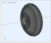
Here your original parameters and then with tmax 1.35.
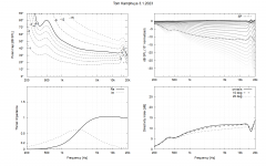
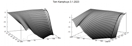
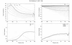
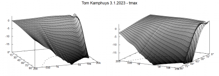
This is almost ideal waveguide, no signs of secondary sounds to any direction except on the top octave.
Wide coverage angle profiles make the R-OSSE curve quite tight so that if a waveguide was constructed with tmax like here driver wouldn't probably fit in. If the definition is adjusted so that the backside is bigger, to get rid of the hump (and diffraction) completely then the curve on the waveguide part seems to approach circular arc which leads to beaming. You have very good definition here though.
I don't know how to manipulate the R-OSSE output, ABEC input, by hand to add custom "backside curve" to have good waveguide profile and nice looking / functioning enclosure on the back for any definition. Perhaps mabat has ideas if this was something that could be implemented in ath?
Although, what we see here is about ideal, game over quality to my eye 🙂
Last edited:
The on-axis hole above 15k will be due to a throat mismatch - most probably you're driving the throat (31°) with a flat wavefront. There's probably not a flat wavefront at the exit of a driver with 31° exit angle but who knows.
I still like the previous one better.Although, what we see here is about ideal, game over quality to my eye 🙂
Last edited:
You can import the file "nodes.txt" into a spreadsheet and modify it any way you like. Those are the coordinates of all the profile points. You only have to keep the order and the total number of them.I don't know how to manipulate the R-OSSE output, ABEC input, by hand to add custom "backside curve" to have good waveguide profile and nice looking / functioning enclosure on the back for any definition.
I could add some "stretching" parameter for the back side. I'm just still not sure it's the best idea.
Last edited:
^^ Yeah probably thats better waveguide in reality. Above are just my quest for zero diffraction, which there are some hints of unless tmax > 1.
Last edited:
Will try, are those just x,y coordinates? inspected the file but points didn't make sense on first glance as they vary weirdly as positive and negative values, expected them all be positive.You can import the file "nodes.txt" into a spreadsheet and modify it any way you like. Those are the coordinates of all the profile points. You only have to keep the order and the total number of them.
I could add some "stretching" parameter for the back side. I'm just still not sure it's the best idea.
I would imagine simplest might be to end R-OSSE curve to t=1 and start another curve from (Xrosse(1),Yrosse(1)) ending up to some adjustable x less than 0 and y=0. Actually y=0 wouldn't probably sim right currently so y=Yrosse(0) for example.I could add some "stretching" parameter for the back side. I'm just still not sure it's the best idea.
Found this from internets, fix (x2,y2) point to (Xrosse(1),Yrosse(1))
https://www.desmos.com/calculator/lavlfhvstv
Or something. Not sure if this is useful for most but at least something to play with. There is probably some diffraction at the junction as the curve wouldn't be continuous like with tmax.. well, you are better to judge all this, tmax is already quite good tool 🙂
Last edited:
Here is Tom's wg as per the definition and then tmaxed.The on-axis hole above 15k will be due to a throat mismatch - most probably you're driving the throat (31°) with a flat wavefront. There's probably not a flat wavefront at the exit of a driver with 31° exit angle but who knows.
I still like the previous one better.
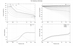
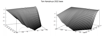
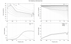
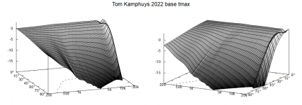
Adding the "back" removes effect of narrowing low end of the waveguide which sound around the waveguide makes and then suitably adjusted diffraction smoothens it out. Side effect of this is some ripple especially on-axis, all the way to high frequencies. At least this is how interpret it. Slight beaming seems to be natural and can be made more constant directivity with the interference. Interference ought to be more audible on bigger waveguides as the bigger the device the more delay there is, its already close to 1ms on these bigger ones. But, the ripple seems so small perhaps its nothing to worry about.
Question for you guys that have modeled plenty of horns on this software, what's the lowest resolution settings you can use before the quality of results degrades too much? I am trying to speed up calculation time to manually optimize the horn design, but since I'm doing a rectangular horn it takes several minutes.
My plan is to first get a uniform beam width in horizontal and vertical plane within 500 - 10kHz, then bring the modeling resolution up to iron out any anomalies. These are my current ABEC settings:
And thank you for this incredible software!!
My plan is to first get a uniform beam width in horizontal and vertical plane within 500 - 10kHz, then bring the modeling resolution up to iron out any anomalies. These are my current ABEC settings:
Code:
ABEC.MeshFrequency = 1000
ABEC.NumFrequencies = 40
ABEC.Polars:SPL_H_ARRAY = {
Distance = 2
FRDExport = {
     NamePrefix = "array_hor"
  }
MapAngleRange = 0,90,72
NormAngle = 0
}
ABEC.Polars:SPL_V_ARRAY = {
Distance = 2
FRDExport = {
     NamePrefix = "array_ver"
  }
Inclination = 270
MapAngleRange = 0,180,72
NormAngle = 0
}

ABEC.SimType = 2
ABEC.f1 = 500
ABEC.f2 = 10000
Horn.Adapter = {
Height = 148
Segments = 0
Width = 37
}
And thank you for this incredible software!!
For a general 3D mesh, there are two/three basic parameters:what's the lowest resolution settings you can use before the quality of results degrades too much?
Mesh.ThroatResolution = 5 ; [mm]
Mesh.MouthResolution = 10 ; [mm]
(Mesh.InterfaceResolution = 8 ; [mm])
The above values give reasonable results in most cases up to 10 kHz. An important value to have an eye on is the total number of elements, shown in ABEC after meshing. I typically try not to exceed 5000, as I don't have a very powerful machine.
- Home
- Loudspeakers
- Multi-Way
- Acoustic Horn Design – The Easy Way (Ath4)
