Here's the curvature for ST260 with tmax=1.1
(The radius is simply a reciprocal value.)

(The radius is simply a reciprocal value.)
Last edited:
If one adds damping / absorption instead of the extra RO, would that have about the same result one wonder...?
//
//
Does it really make sense to trade what looks like maybe 0.25 dB of ripple for a lumpier low end response?Trade-off that happens with OS-SE script rollback angle manipulation seems to be more interference on lower frequencies.
Yeah probably not, just toying around if its possible to make textbook response 😉
ps. I see the high frequency ripple appears because there is some high frequency radiation to the edge. Basically this is side effect the waveguide not beaming, waveguide being good. So its the usual reduce sound to the edge or reduce the edge situation. Like in all loudspeaker stuff we are combating the varying wavelength with static sized object so its probably about as good as it gets without the extra rollback, good balance between effect on lows and highs. Still, fun to experiment with it and try to imagine why the more rollback makes more ripple and is there ways around it.
0.25db p-p ripple happens when two sounds roughly 35db apart interfere so diffraction related sound on-axis its quite little. Expressed like distortion its less than 0.1% but more than 0.01% 🙂
Last edited:

All right imagination reserves used for today, here is where I got speculating over the responses:
So the question is why there is this off-axis low frequency ripple increasing as rollback is extended to further than 180deg? Quick look it has similar features on the graphs as typical baffle edge diffraction. Assuming its diffraction why there looks to be less off a ripple with effectively less roundover? We know the roundover needs to be big in comparison to wavelength to be effective, so it would be logical that making roundover "bigger" the diffraction related ripple would reduce and indeed it does at least on the higher frequencies.
I speculate diffraction happens also on the cleanest looking 180 deg rollback but what we see on the graphs is diffraction and sound that goes around the waveguide cancel out some. There is little that "reflects back" due to diffraction on the edge and similarly little that goes around the edge. What happens when rollback is increased the balance goes off and there is seemingly more diffraction although I speculate there is less diffraction and what we see is sound going around the waveguide.
ATH standard report shows off-axis response only to 90deg but VACS shows all the way to 180deg. Here is waveguide whose depth is 72mm and diameter about 200mm, so path length difference around the waveguide to 90deg angle is roughly diameter of the device, so about perhaps 20cm in this case. This would show as constructive interference 90deg off-axis where wavelength is ~20cm and destructive interference where wavelength is ~40cm.

180deg behind the waveguide output is strong as sound around both (all) sides sum there constructively. Basically this looks similar what we see on box BEM sims, sound around the box makes nulls to high off-axis angles. The waveguide is almost flat in comparison to the diameter of the waveguide so cancellation starts already below 90 deg angles.
Here's illustration of diffraction cancelling sound around the waveguide theory.

If assume this is correct how it plays out then we could try foam behind the waveguide. Use big/extended roundover to reduce diffraction and use foam block behind the waveguide to reduce sound around the waveguide. Or just make bullet/sphere shaped enclosure or something, alongate the structure to increase path length around it and turn the ridge further off-axis (on pass band) that no shows up here around 1kHz. There might also be possibility to manipulate the roundover so that diffraction / pathlegth stuff stays balanced for the low frequencies but is reduced for the high frequencies, perhaps just manufacture thick round edge on the 180deg wg.
On the other hand all this is quite academic as noted, the ripple that looks to be diffraction is very low on ST260 for example and there is no way to prevent sound propagating around the device unless it is in-wall system (bigger than wavelengths on the pass band) so features on frequency responses we see here is something we have to live with anyway. Its probably better to optimize for good DI than agonize over miniscule diffraction.
What is interesting though, that it looks to my eye that waveguide with extended roundover seems diffraction free 🙂
So the question is why there is this off-axis low frequency ripple increasing as rollback is extended to further than 180deg? Quick look it has similar features on the graphs as typical baffle edge diffraction. Assuming its diffraction why there looks to be less off a ripple with effectively less roundover? We know the roundover needs to be big in comparison to wavelength to be effective, so it would be logical that making roundover "bigger" the diffraction related ripple would reduce and indeed it does at least on the higher frequencies.
I speculate diffraction happens also on the cleanest looking 180 deg rollback but what we see on the graphs is diffraction and sound that goes around the waveguide cancel out some. There is little that "reflects back" due to diffraction on the edge and similarly little that goes around the edge. What happens when rollback is increased the balance goes off and there is seemingly more diffraction although I speculate there is less diffraction and what we see is sound going around the waveguide.
ATH standard report shows off-axis response only to 90deg but VACS shows all the way to 180deg. Here is waveguide whose depth is 72mm and diameter about 200mm, so path length difference around the waveguide to 90deg angle is roughly diameter of the device, so about perhaps 20cm in this case. This would show as constructive interference 90deg off-axis where wavelength is ~20cm and destructive interference where wavelength is ~40cm.
180deg behind the waveguide output is strong as sound around both (all) sides sum there constructively. Basically this looks similar what we see on box BEM sims, sound around the box makes nulls to high off-axis angles. The waveguide is almost flat in comparison to the diameter of the waveguide so cancellation starts already below 90 deg angles.
Here's illustration of diffraction cancelling sound around the waveguide theory.
If assume this is correct how it plays out then we could try foam behind the waveguide. Use big/extended roundover to reduce diffraction and use foam block behind the waveguide to reduce sound around the waveguide. Or just make bullet/sphere shaped enclosure or something, alongate the structure to increase path length around it and turn the ridge further off-axis (on pass band) that no shows up here around 1kHz. There might also be possibility to manipulate the roundover so that diffraction / pathlegth stuff stays balanced for the low frequencies but is reduced for the high frequencies, perhaps just manufacture thick round edge on the 180deg wg.
On the other hand all this is quite academic as noted, the ripple that looks to be diffraction is very low on ST260 for example and there is no way to prevent sound propagating around the device unless it is in-wall system (bigger than wavelengths on the pass band) so features on frequency responses we see here is something we have to live with anyway. Its probably better to optimize for good DI than agonize over miniscule diffraction.
What is interesting though, that it looks to my eye that waveguide with extended roundover seems diffraction free 🙂
Last edited:
Cycling 180deg and 220deg rollback versions quickly its easy to see the there is two sets of ripple, diffraction related and something else. The diffraction related ripple seems to coincident with the other ripple making it less. See the ridge around 1kHz, easier to see on the left view.


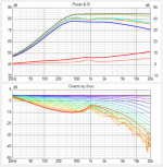
This is the ST260W with tmax = 1, 1.1 and 1.2:


Maybe it could be re-optimized (e.g. for t=1.1), who knows.
Maybe it could be re-optimized (e.g. for t=1.1), who knows.
This is what my optimizer spitted out. It will be ugly but it should work pretty well. Nominal coverage 110°.Maybe it could be re-optimized (e.g. for t=1.1), who knows.
R = 130
a = 50
a0 = 15
b = 0.38
k = 1.18
m = 0.72
q = 3.20
r = 0.26
r0 = 12.7
tmax = 1.1
Hey guys, just some troubleshooting, since I messed up something on the code.
I've been able to figure out how to generate a rectangular throat, and it generates the stl and mesh files fine. I just cannot get it to read in VACS after I run the solver and spectra in ABEC3. After I run the spectra calculation, VACS remains blank. The model in the 'Drawing' tab of ABEC3 also doesn't show the red source element in the throat, so I think that's the problem.
I copied off a line array horn that had multiple circular sources, and tried to just make a single rectangular source (using Elem.Shape=1) to match the size of the throat.
Code:
; Ath version 4.9.0-pre-release-221114
; Created: 2022-11-14 13:28
ABEC.MeshFrequency = 1000
ABEC.NumFrequencies = 40
ABEC.Polars:SPL_H_ARRAY = {
Distance = 2
FRDExport = {
     NamePrefix = "array_hor"
  }
MapAngleRange = -180,180,72
NormAngle = 0
}
ABEC.Polars:SPL_V_ARRAY = {
Distance = 2
FRDExport = {
     NamePrefix = "array_ver"
  }
Inclination = 270
MapAngleRange = -180,180,72
NormAngle = 0
}

ABEC.SimType = 2
ABEC.f1 = 200
ABEC.f2 = 15000
Horn.Adapter = {
Height = 148
Segments = 0
Width = 37
}

Horn.Part:1 = {
H = {
a = 73
a0 = 3
k = 5.05
n = 2
q = 0.996
r0 = 74
s = 1.0
}

L = 1
Segments = 16
V = {
a = 10
a0 = 0
k = .5
n = 2
q = 0.996
r0 = 18.5
s = 0.7
}
ZMap = 0.5,0.3,0.5,0.9
}

HornGeometry = 2
Length = 100
Mesh.AngularSegments = 64
Mesh.InterfaceOffset = 0
Mesh.InterfaceResolution = 6
Mesh.MouthResolution = 12
Mesh.RearResolution = 25
Mesh.SubdomainSlices = -2
Mesh.ThroatResolution = 6
Mesh.WallThickness = 10
Mesh.ZMapElementSize = 0.3,0.6,0.5,0.95

Output.ABECProject = 1
Output.STL = 1

Source.Array = {
Elem.Group = 1
Elem.Shape = 1
Elem.Width = 37
Elem.Height = 148
}

Throat.Angle = 0
Throat.Diameter = 37Almost there 😀 Its beaming a bit, it needs to fit inside the driver conical throat. R=130, proof of concept, not sure how well this would mate with a woofer.


Last edited:
If you want the whole rectangular throat area as the driving element, don't define Source.Array, just omit it. That's used only for discrete element array (smaller circles or rectangles) within this area, optionally set into groups.I copied off a line array horn that had multiple circular sources, and tried to just make a single rectangular source (using Elem.Shape=1) to match the size of the throat.
Last edited:
Yeah, don't buy drivers with long throats anyone 🙂 Takeaway is that its possible to get rid of diffraction while still having smooth DI.
btw. here it is simmed with real measured cardioid mid and I think it works just fine. Beaming is visible but overall smooth response so cannot comment is it good or bad before hearing
btw. here it is simmed with real measured cardioid mid and I think it works just fine. Beaming is visible but overall smooth response so cannot comment is it good or bad before hearing
Attachments
Last edited:
Of course it is, see the ST280E: https://www.diyaudio.com/community/...-design-the-easy-way-ath4.338806/post-6760695Takeaway is that its possible to get rid of diffraction while still having smooth DI.
- Home
- Loudspeakers
- Multi-Way
- Acoustic Horn Design – The Easy Way (Ath4)