The same horn as above in an infinite baffle:BTW, this is the final "2P" horn I'm going to actually build and test (640 x 476 x 340 mm, 1.5" throat): ...
Guys, this is what it has been all about for hundreds of pages of this thread already, since the dawn of the OS-SE formula ")
In the case of the QT, curvature of the arc is simply the inverse of its radius (i.e. curvature = 1/R).
For a general curve it is intuitively analogous - it's the inverse of the radius of the "best fitting" circle at a given point.
For a straight line it is of course zero.
In the case of the QT, curvature of the arc is simply the inverse of its radius (i.e. curvature = 1/R).
For a general curve it is intuitively analogous - it's the inverse of the radius of the "best fitting" circle at a given point.
For a straight line it is of course zero.
Last edited:
Finally, templates for cutting the flexi boards - it must be a miter joint, there's no other way around.

The board is cut along the outer edge and then grinded off to the inner edge (or cut on CNC).
Along with a 3D printed throat adapter, it would make for a nice construction set. I would have to think it through...
The board is cut along the outer edge and then grinded off to the inner edge (or cut on CNC).
Along with a 3D printed throat adapter, it would make for a nice construction set. I would have to think it through...
Last edited:
Yes, from the start I've been under the impression this thread has been about the pursuit of the most theoretically perfect results attainable.Guys, this is what it has been all about for hundreds of pages of this thread already, since the dawn of the OS-SE formula
And is why I ask how much would the insertion of straight walled sides between a throat adapter and curved mouth, in fact hurt.
I guess I'm asking can ATH model such?
Because I'd love to get an idea of how much I'm leaving on the table by not striving for OS perfection for the CD, in order to gain the overall point source properties a synergy provides across a wider bandwidth (than a CD alone can cover). Thx.
Yes, you can do it with ATH. I haven't tried to optimize any but from the attempts I made it was pretty clear that it's simply worse.
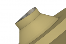
This is an example with the outer dimension very similar to the horn above (free standing):


Perhaps it could be further improved, I just don't know.
This is an example with the outer dimension very similar to the horn above (free standing):
Perhaps it could be further improved, I just don't know.
Thank you very much !Yes, you can do it with ATH. I haven't tried to optimize any but from the attempts I made it was pretty clear that it's simply worse.
This is an example with the outer dimension very similar to the horn above (free standing):
View attachment 1089272 View attachment 1089273 View attachment 1089274
Perhaps it could be further improved, I just don't know.
You can see in the simulation mabat did below and in the one's I ran before on a big conical with and without a secondary flare what you miss out on. Better smoother pattern control and less diffraction generally. What you have to ask yourself is how much do those things matter when the horn itself is big enough and point source enough. From your own experience you said didn't notice any real difference in sound between secondary flare on or off but it measured better and more consistently with it on.Because I'd love to get an idea of how much I'm leaving on the table by not striving for OS perfection for the CD, in order to gain the overall point source properties a synergy provides across a wider bandwidth (than a CD alone can cover). Thx.
Only the mounting flange for the driver needs to be flat. The horn can have a slight curve without making it difficult to attach the driver but fabricating the mounts would need a CNC/3D printer or manual labour like bushmeister did with his.
Yep. You surmise my thoughts well. I guess the real motivation behind my questions/doubts is simply looking for a toehold for further improvement.You can see in the simulation mabat did below and in the one's I ran before on a big conical with and without a secondary flare what you miss out on. Better smoother pattern control and less diffraction generally. What you have to ask yourself is how much do those things matter when the horn itself is big enough and point source enough. From your own experience you said didn't notice any real difference in sound between secondary flare on or off but it measured better and more consistently with it on.
The LCR project talked about in the other thread has been my new frontier, because i feel stymied on how to improve the syns themselves any further.
And yes again, I haven't heard enough difference with secondary flares to make the extra work and size and weight worth the effort. But then, maybe i'm just deaf ....because I don't even hear a difference with the best throat to CD matching I can do vs leaving round to square alone.
I've looked at mounting drivers to various commercial horns like bushmeister did. It's clearly viable.Only the mounting flange for the driver needs to be flat. The horn can have a slight curve without making it difficult to attach the driver but fabricating the mounts would need a CNC/3D printer or manual labour like bushmeister did with his.
One downside is any curvature lengthens the ports, which begs they be a little bigger, which mucks a little more with polars. But all that still might make for a good tradeoff, vs plain straight walls.
...a good adapter will at least match the tangent angles of the boards perfectly. I figured out how to do it and implemented this recently but I'm not yet sure I want to make it public domain -
I'm not sure if what your doing is exactly the same but I believe I have already posted code that does this for the joining of exponential sections to conic sections in an attempt make expoential-conic horns without wall angle discontinuity.
Greetings all,
And another option: https://www.diyaudio.com/community/...-mid-in-unity-horn.88237/page-50#post-3529953
Kindest regards,
M
mabat said:
...a good adapter will at least match the tangent angles of the boards perfectly. I figured out how to do it and implemented this recently but I'm not yet sure I want to make it public domain -
I'm not sure if what your doing is exactly the same but I believe I have already posted code that does this for the joining of exponential sections to conic sections in an attempt make expoential-conic horns without wall angle discontinuity.
And another option: https://www.diyaudio.com/community/...-mid-in-unity-horn.88237/page-50#post-3529953
Kindest regards,
M
I think the practical difference is pretty small but there aren't really many good commercial horns to buy.I've looked at mounting drivers to various commercial horns like bushmeister did. It's clearly viable.
One downside is any curvature lengthens the ports, which begs they be a little bigger, which mucks a little more with polars. But all that still might make for a good tradeoff, vs plain straight walls.
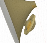
Some screenshots of a port design in a fairly high curvature waveguide. There is a bit more throat volume from the frustrum section but the port can be quite short.
Attachments
Hi fluid, mark100,

Although this is for Aura NSW2, even bigger close fitting driver-to-wave-guide can be fashioned. And without CNC, CAD 3D printers.

Of course, the big advantage of CAD, 3D printing is the ability to adjust the drawing parameters and re-print, if the measurement does not confirm the theory.
Kindest regards,
M
With the power of CAD and 3D printers, why not make an adapter closely attached for the wave-guide?Some screenshots of a port design in a fairly high curvature waveguide. There is a bit more throat volume from the frustrum section but the port can be quite short.
Although this is for Aura NSW2, even bigger close fitting driver-to-wave-guide can be fashioned. And without CNC, CAD 3D printers.
Of course, the big advantage of CAD, 3D printing is the ability to adjust the drawing parameters and re-print, if the measurement does not confirm the theory.
Kindest regards,
M
Last edited:
My images were illustrative as they are the inner surfaces used for a BEM model. In a real implementation they would be cut out of a solid block made to fit the back of the waveguide as you show.Hi fluid, mark100,
With the power of CAD and 3D printers, why not make an adapter attached for the wave-guide?
Hi M, hi fluid,Hi fluid, mark100,
With the power of CAD and 3D printers, why not make an adapter closely attached for the wave-guide?
View attachment 1089959
Although this is for Aura NSW2, even bigger close fitting driver-to-wave-guide can be fashioned. And without CNC, CAD 3D printers.
View attachment 1089960
Of course, the big advantage of CAD, 3D printing is the ability to adjust the drawing parameters and re-print, if the measurement does not confirm the theory.
Kindest regards,
M
Good stuff guys. Thx for the examples.
Must admit I have problems with the ideas of adapters, if they require an increase in the total port length from the inner horn wall to the cone, and/or they increase the volume between the cone and out horn wall.
Maybe adapters work fine...i've just never tried any, because I've found minimizing both the port length, and volume under the cone to be real advantages.
M, i really like the way the mounting surface cuts into the horn on your second pict.
I can see that can work for smaller drivers.. For larger drivers, it seems driver diameter vs any horn curvature, is going make doing so pretty tough.
But i think ultimately, that's what it might take.
Hi mark100,
Once one has designed the horn/wave-guide, the injection ports size, and selected the drivers, the added volume can be calculated. In any event, should the added volume be a problem, it can be solved by fashioning a volume reducer.
I also understand, but was unable to figure out how to model it yet, there is a relationship between the under-the-cone volume and the size of the injection ports, that may mitigate the problem. Maybe fluid will know how to model/optimize it.
Kindest regards,
M

I might be mistaken, as I mostly am, but it seems to me that you are neglecting the fact that the bigger driver is further from the throat and, thus the higher rate of curvature. I am attaching an old drawing from my initial thinking about the issue. Note that the volume between the cone and the wall is increased by the volume of the injection port, which is a function of the curvature (generally along all three axes), the size of the injection port, and the diameter of the driver.I can see that can work for smaller drivers.. For larger drivers, it seems driver diameter vs any horn curvature, is going make doing so pretty tough.
Once one has designed the horn/wave-guide, the injection ports size, and selected the drivers, the added volume can be calculated. In any event, should the added volume be a problem, it can be solved by fashioning a volume reducer.
I also understand, but was unable to figure out how to model it yet, there is a relationship between the under-the-cone volume and the size of the injection ports, that may mitigate the problem. Maybe fluid will know how to model/optimize it.
Kindest regards,
M
Last edited:
Hi kipman725,
One can then measure the wall thickness and arrive at the entire profile.
In an alternative, one can chuck the wave-guide into a lathe (provided enough clearance) and use the tool holder for attaching the indicator. The later has an advantage in that if one does not have a two-axes indicator, the measurements of non-axi-symmetric horn can be made quicker by rotating the wave-guide along the z-axes.
Kindest regards,
M
The way I did it, was to mount the wave-guide on a milling-machine table. I then chucked a dial indicator into the spindle and indicated zero on, e.g., the throat. I was then raising the spindle with the dial indicator by a pre-determined delta (let us call it in z-axes), moved the table in the x/y axes, until the indicator read zero again and read the delta between the previous position and the new one.how are you able to measure and create a 3D model of the horn for off the shelf horns?
One can then measure the wall thickness and arrive at the entire profile.
In an alternative, one can chuck the wave-guide into a lathe (provided enough clearance) and use the tool holder for attaching the indicator. The later has an advantage in that if one does not have a two-axes indicator, the measurements of non-axi-symmetric horn can be made quicker by rotating the wave-guide along the z-axes.
Could you please explain your response in a manner of talking to an idiot?what about continuously expanding adapters? (helmholz frequency increased), an engineered mesh could be used at the horn inner surface to 'hide' the tap from the compression driver
Kindest regards,
M
Hi mark100,
I might be mistaken, as I mostly am, but it seems to me that you are neglecting the fact that the bigger driver is further from the throat and, thus the higher rate of curvature. I am attaching an old drawing from my initial thinking about the issue. Note that the volume between the cone and the wall is increased by the volume of the injection port, which is a function of the curvature (generally along all three axes), the size of the injection port, and the diameter of the driver.
Once one has designed the horn/wave-guide, the injection ports size, and selected the drivers, the added volume can be calculated. In any event, should the added volume be a problem, it can be solved by fashioning a volume reducer.
I also understand, but was unable to figure out how to model it yet, there is a relationship between the under-the-cone volume and the size of the injection ports, that may mitigate the problem. Maybe fluid will know how to model/optimize it.
Kindest regards,
M
View attachment 1090148
You are saying what i meant to be saying, that a larger diameter driver will make for a longer injection port, especially as the curvature of the horn increases. Which like you point out, is what happens due to larger drivers needing to mount further from the throat, and more towards the mouth.
Sorry i wasn't clear enough to follow.
- Home
- Loudspeakers
- Multi-Way
- Acoustic Horn Design – The Easy Way (Ath4)