It is hard to say if there would always be an increase in either as the effective length of the port can be changed through the frustrum but that in turn adds an amount of throat chamber volume. Whether that is significant would depend on the driver size, a couple of cc's might not matter on a 15" but it might be on a 2", but when making an adapter a chamber filling part could be added to offset any increase. So it would be very dependent on how the horn curves and where.Must admit I have problems with the ideas of adapters, if they require an increase in the total port length from the inner horn wall to the cone, and/or they increase the volume between the cone and out horn wall.
Maybe adapters work fine...i've just never tried any, because I've found minimizing both the port length, and volume under the cone to be real advantages.
I think the more difficult part for using large drivers in large optimized horns would be making the horn wall stiff enough to mount the driver without issue. Making a horn out of bended ply to form the shape is a bit different than trying to hang a 15" woofer off it.
Could be post the config file or explain what to change to set a central conical section?Yes, you can do it with ATH. I haven't tried to optimize any but from the attempts I made it was pretty clear that it's simply worse.
Code:
; Flat center boards - Ath 4.9

HornGeometry = 2
Length = 100
Throat.Diameter = 40
Throat.Angle = 0

Horn.Adapter = {
  L = 50
  k = 2
  Width = 80
  Height = 60
  SC = 0
  Segments = 10
  ZMap = 0.5,0.4,0.5,0.5
}

Horn.Part:1 = {
  L = 240
  Segments = 1
  H = {
    r0 = 50
    a0 = 32
    k = 0
    s = 0
    a = 40
  }
  V = {
    r0 = 30
    a0 = 24
    k = 0
    s = 0
    a = 30
  }
  ZMap = 0.3,0.3,0.7,0.7
}

Horn.Part:2 = {
  L = 40
  Segments = 6
  H = {
    r0 = 20
    k = 0
    s = 1.2
    n = 2
    q = 0.996
    a = 40
  }
  V = {
    r0 = 20
    k = 0
    s = 1.3
    n = 2
    q = 0.996
    a = 30
  }
  ZMap = 0.5,0.5,0.5,0.9
}

; -------------------------------------------------------

Mesh.AngularSegments = 64
Mesh.ThroatResolution = 5
Mesh.MouthResolution = 14
Mesh.InterfaceResolution = 7
Mesh.RearResolution = 25
Mesh.SubdomainSlices = -2
Mesh.InterfaceOffset = 0
Mesh.WallThickness = 10
Mesh.ZMapElementSize = 0.3,0.6,0.5,0.95

ABEC.SimType = 2
ABEC.f1 = 200 ; [Hz]
ABEC.f2 = 15000 ; [Hz]
ABEC.NumFrequencies = 40
ABEC.MeshFrequency = 1000 ; [Hz]

ABEC.Polars:SPL_H = {
  MapAngleRange = 0,180,37
  Distance = 2
}

ABEC.Polars:SPL_V = {
  MapAngleRange = 0,180,37
  Distance = 2
  Inclination = 90
}

; -------------------------------------------------------

Report = {
  Title = "Flat"
  PolarData = SPL_H
  NormAngle = 5
  Width = 1400
  Height = 800
}

Output.STL = 1
Output.ABECProject = 1
Thanks for that, what does SC stand for and r0 and a0? I looked at the OSSE and R-OSSE terms but I couldn't work it out in this context.
You can ignore/omit SC. The H and V sections in Horn.Part are all OSSE sections (automatically connected together), so r0 and a0 have no use in this context (i.e. when k = 0) and can be left out. If k > 0 then both would have their meaning of course.
This makes a flat wall at the defined angle:
k = 0
s = 0
a = 40 ; wall angle [deg]
This makes a flat wall at the defined angle:
k = 0
s = 0
a = 40 ; wall angle [deg]
Next step would be calculate gcode directly using: https://fullcontrolgcode.com/
https://fullcontrol.xyz/
I informed Andy about this thread. Large overhangs possible.
https://fullcontrol.xyz/
I informed Andy about this thread. Large overhangs possible.
I'm happy with the Fusion scripts so far. It gives a complete freedom to the overall construction.

Whatever floats your boat. I just don't see a reason for that.
- Starting some experiments:

- Starting some experiments:
Last edited:
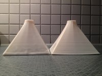
The transition round->rectangle looks great! That is your new attempt? Seems less „sectionized“
No, it's a regular print. It's just an OS-based shape, there's really no reason to use anything else I think. The continuously decreasing curvature being an advantage, it's almost zero at the exit.

Last edited:
I’m not claiming that ours are the same but there’s definitely similarities.No, it's a regular print. It's just an OS-based shape, there's really no reason to use anything else I think. The continuously decreasing curvature being an advantage, it's almost zero at the exit.
View attachment 1091731
I made a approximation of the quadratic-throat waveguide in my synergy horn. (https://peaveycommercialaudio.com/w...atic-Throat-Waveguide-by-Charles-E-Hughes.pdf)
The opening angle starts at the mounting plate for the BMS 4550 and some wood was taken away by cnc and I printed thin plates in ABS where material was added.
Attachments

Yea, I think this was mentioned already. It's similar in the same way as quadratic throat is similar to OS. QT is an approximation (simpler and less smooth). How much is it different acoustically would need to be tested. Since the QT discontinuity is still quite close to the throat (and spatially distributed in this case), I believe it doesn't necessarily mean much.
Last edited:
At this level, the driver's exit <> throat 'interface' is potentially more disturbing.
True, Olson made similar comments in the 1950s.
The continuously decreasing curvature being an advantage, it's almost zero at the exit.
True, Olson made similar comments in the 1950s.
The acoustic impedance doesn't care if the shape is a square or a circle or a transitioning form, as long as the area increases with the same rate.
Perhaps in extreme cases (not HF horns) where the air flow is strong - it could drag more in the corners creating turbulences.
Perhaps in extreme cases (not HF horns) where the air flow is strong - it could drag more in the corners creating turbulences.
If the driver's exit section is conical and relatively long I think there will always be some reflection at the driver/throat interface. As it typically doesn't affect the radiation pattern too much, I don't see this as critical even if it's relatively strong - these things can be corrected on signal level.
That said, it's still the best to avoid the conical section completely. Sometimes it can be done, some drivers don't have any (and even then there's the phase plug).
That said, it's still the best to avoid the conical section completely. Sometimes it can be done, some drivers don't have any (and even then there's the phase plug).
Last edited:
- Home
- Loudspeakers
- Multi-Way
- Acoustic Horn Design – The Easy Way (Ath4)