Regarding the area expansion, actually I don't know, have never seen it mentioned anywhere.
It's not obvious to me from such pictures.
It's not obvious to me from such pictures.
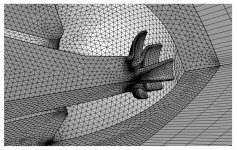
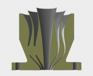
I read this paper yesterday for different reasons, but noticed with curiosity the results >10 kHz that are obtained in the data when the author added a representation of the compression driver phase plug channels to the apex of the horn. It looks like they’re using a ‘generic’ type for the purposes of comparing horn simulations, with a planar-driven element at the end of each phase plug ‘channel’:
http://www.speakerlab.it/resources/HCD.pdf
Perhaps this might be a good ‘start condition’ option for Ath, rather than trying to make LE models of various compression drivers? They are using thermoviscous acoustics models in those channels, but I think the results without would still be of interest. Also it was kind of amusing how the shape shown is kind of the inverse of all the vane stuff that's been over the last few pages 🙂
Attachments
I don't see how could that be of any help. What's the difference between using a simple flat (or whatever) wavefront and using a 'generic' phase plug? In both cases you are only assuming how the wavefront really looks like, the later being only a lot more complex.
The LE model includes also the electric and mechanical parts, allowing to predict the absolute efficiency, diaphragm excursion, etc. That's the main reason why I would use it.
The LE model includes also the electric and mechanical parts, allowing to predict the absolute efficiency, diaphragm excursion, etc. That's the main reason why I would use it.
Kind of, not quite an inverse. It would be probably better to start the vanes right at the diaphragm (as was already discussed in the past) but that would mean a fresh new developmnet of a larger part of the acoustic path for a chosen driver. So my current approach just assumes a flat wavefront at the exit of an existing driver. Hopefully they come close enough. If they don't, it won't work very well.Also it was kind of amusing how the shape shown is kind of the inverse of all the vane stuff that's been over the last few pages 🙂
Last edited:
The UPA-1A uses/used the MS-1401A compression driver. Go to this link, picture 4: 403 Forbidden
Those drivers are made in-house so technical details on them should be scarce. But I don’t see a bug screen.
Those are modified Yamaha JA6681b drivers and they do have a bug screen, as does the originals.
//Anders
You’re correct that those were originally Yamaha drivers; the design dates to before my time there. Do you know if bug screen removal was not part of the modification process? I have yet to see any online images of a MS-1404A with a bug screen.
I can’t speak freely about this due to my past employment at said company and the NDA I signed except to say that I was fully aware of Earl’s patent on the use of open-cell foam in horns at the time of my employment and that if I had any reason to believe they were infringing on his patent I wouldn’t feel comfortable addressing the topic at all.

I can’t speak freely about this due to my past employment at said company and the NDA I signed except to say that I was fully aware of Earl’s patent on the use of open-cell foam in horns at the time of my employment and that if I had any reason to believe they were infringing on his patent I wouldn’t feel comfortable addressing the topic at all.
Yea, that's it. The technical document described the use of foam in the throat. You can see it in that picture. Apparently not worth patenting!?
Meyer sound uses the foam piece only in the middle part of their waveguide. The foam does not Reach the compression driver exit. I have those speakers and can provide some more information. For the later modifications Meyer sound abandoned the use of foam and switched to a different compression driver and a different horn.
It would be probably better to start the vanes right at the diaphragm (as was already discussed in the past) but that would mean a fresh new developmnet of a larger part of the acoustic path for a chosen driver. So my current approach just assumes a flat wavefront at the exit of an existing driver. Hopefully they come close enough. If they don't, it won't work very well.
There’s an example of the wavefront across a plane at the throat in the model shown in that paper, and unfortunately it doesn’t appear to be planar for that example, at least.
I have ownwed both the Yamaha and the Meyer and they all had bug screens. If that's the case for all Meyer modified drivers, I don't know.
Nice drivers though, a shame that it's impossible to get new diaphragms for them!
//Anders
Nice drivers though, a shame that it's impossible to get new diaphragms for them!
//Anders
No one is saying it's easy 🙂There’s an example of the wavefront across a plane at the throat in the model shown in that paper, and unfortunately it doesn’t appear to be planar for that example, at least.
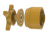
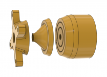
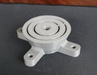
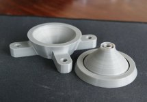
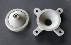
Working on a 1" device: Fusion 3D Model Visualization
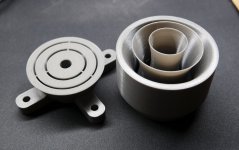
Printed in three parts. The throat aperture is only ⌀16.6 mm as there's a tubular insert (#8818).
Printed in three parts. The throat aperture is only ⌀16.6 mm as there's a tubular insert (#8818).
Attachments
Last edited:
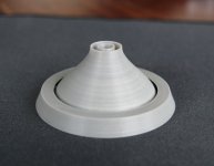
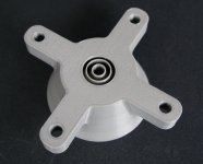
The prints so far (0.25 mm nozzle, 0.1 mm layer), definitely usable. With that nozzle I get to ~0.55 mm wall thickness (two perimeters).
Attachments
Last edited:
The prints look really great! Only the bottom maybe looks like the nozzle could be a wee bit closer to the bed for the first layer.
You have eyes of an expert. Yeah, I've adjusted that a bit in the meantime. These are actually still the very first prints on my Kingroon KP3S and I love it already, a nice little printer, I should have bought two for the price.
So I have some good news and some bad news.
The good news is that the phase plug actually spreads the HF and improves loading.
Bad news is that it also introduces some peaks and dips. Especially on axis
It's remarkable, but also a bit sad, to see that the concept of loading has now become a significant factor in this thread, while not too long ago (horn) loading was frequently dismissed as completely irrelevant and obsolete.
The current discussion lacks fundamental research that could speed up developments. But there's a lot to learn the hard way, as it turns out.
Last edited:
That's a plain lie -[...] not too long ago (horn) loading was frequently dismissed as completely irrelevant and obsolete.
mabat said:Achieve both, high loading and controlled directivity, is the Holy Grail of waveguide design. No one yet has really succeded (i.e. without serious drawbacks), as far as I know. I'll take the better directivity anytime. (#6248)
It's remarkable, but also a bit sad, to see that the concept of loading has now become a significant factor in this thread, while not too long ago (horn) loading was frequently dismissed as completely irrelevant ...
I think that the current discussion of "loading" is completely different than the previous ones. What Marcel is doing is well worth consideration, whereas previous discussions were all academic around how the flare rate affects "loading" and the need for good loading to minimize distortion. These factors are irrelevant, however Marcels approach adding a few dB of gain at the lower edge of the passband in a device with controlled directivity is a great secondary effect.
- Home
- Loudspeakers
- Multi-Way
- Acoustic Horn Design – The Easy Way (Ath4)