Hi everybody,
Sorry to interrupt with a silly question, but I'm wondering if it could be possible to define both a horizontal and a vertical coverage angle in ATH to obtain a horn with a desired 60°x40° constant directivity pattern ? Because as far as I know I think it is only possible to define one coverage angle.
Best,
Ewen
In a general 3D case, providing values for horizontal and vertical angles is still not enough, as there is an infinite number of ways what can be in between - you have to provide values for all the angles and there are two ways how to do that: either with a guiding curve (GCurve.*), or with the explicit Coverage.Angle definiton, which can be any mathematical expression using a parameter 'p' which is the inclination angle (0 - 360°), possibly together with all the other OS-SE parameters varying as well.
You can create some really weird shapes this way. You can also combine it with the Morph.* feature which smoothly transforms any shape to have a rectangular mouth.
ATH - Advanced Transition Horns - Gallery
You can create some really weird shapes this way. You can also combine it with the Morph.* feature which smoothly transforms any shape to have a rectangular mouth.
ATH - Advanced Transition Horns - Gallery
Last edited:
Have you tried to compare the results of simulating a pulsating sphere instead of the phase plug on the same horn?
Sure -
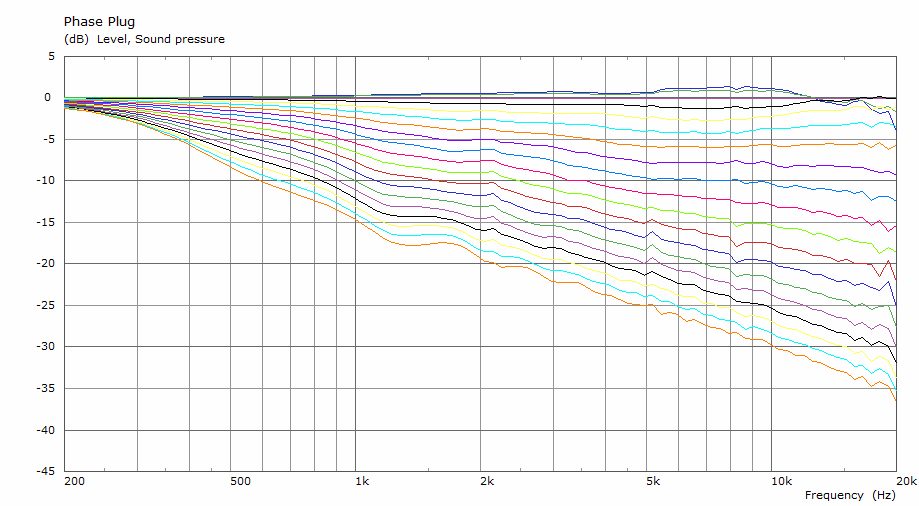
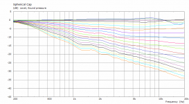
The "phase plug" (50x5V2), polars normalized to 10 deg, 0-90/5 deg:
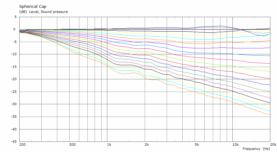
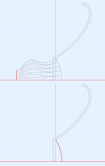
The corresponding pulsating spherical cap (ø106 mm in this case - see the attached drawing):
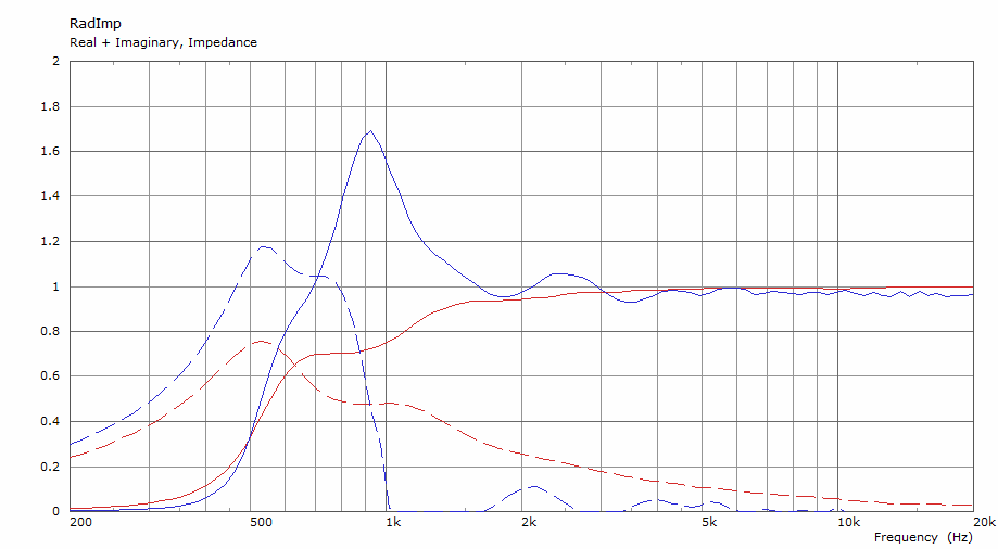
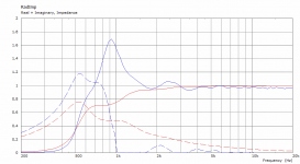
Normalized impedances (blue=phase plug):
The "phase plug" (50x5V2), polars normalized to 10 deg, 0-90/5 deg:
The corresponding pulsating spherical cap (ø106 mm in this case - see the attached drawing):
Normalized impedances (blue=phase plug):
Attachments
Last edited:
To me this means that a waveguide optimized for a given spherical wavefront source will perform basically the same with the corresponding "phase plug" (still need to come up with a suitable name), i.e. it's possible to design it separately. At least the polar performace. The impedance (and the absolute SPL response) will still be affected by the details of the interface.
Last edited:

Sure -
The "phase plug" (50x5V2), polars normalized to 10 deg, 0-90/5 deg:
The corresponding pulsating spherical cap (ø106 mm in this case - see the attached drawing):
Normalized impedances (blue=phase plug):
The radiation impedance has doubled, i.e. greater "loading", and yet there is no change in the radiated output. Looks like "loading" is not really a factor after all.
The polar output charts are normalised to the on-axis response in those most recent plots, so the increased loading at 800 Hz is possibly just 'masked' by the way the magnitude data is shown?
Given that it's a relatively narrow band loading peak, it would probably just need to be equalised out, though.
Given that it's a relatively narrow band loading peak, it would probably just need to be equalised out, though.
The radiation impedance has doubled, i.e. greater "loading", and yet there is no change in the radiated output. Looks like "loading" is not really a factor after all.
Earl those graphs are normalized polar plots converted to curves and so they will only show the directivity not the SPL gain of the extra RadImp at lower frequencies.
mabat could plot the SPL curves and they would look different.
edit: didn't see kyle's post.

I don't see normalization as an answer. I thought about that and decided that it wouldn't be the case. The increased loading is band-limited and as such should affect even a normalized plot. But there is no difference what-so-ever around 800 Hz.
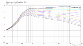
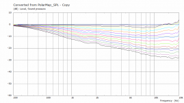
These are the non normalized polar curves where you see the effect of the extra RadImp on the lower frequencies.
We need to see a comparison between the two.
It's a comparison of quite different sources, one of them being purely theoretical. I was only interested in the radiation pattern for that kind of analysis.
Regarding the horn "loading", I already showed a relevant example and it's not a small effect: Acoustic Horn Design – The Easy Way (Ath4) (#8624).
Regarding the horn "loading", I already showed a relevant example and it's not a small effect: Acoustic Horn Design – The Easy Way (Ath4) (#8624).
Those curves are for a constant velocity source. I'm not sure it's very relevant either.These are the non normalized polar curves where you see the effect of the extra RadImp on the lower frequencies.
Best I can do is show normal vs non normal, third image is a gifWe need to see a comparison between the two.
Attachments

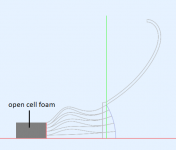
The idea is that at least some of the wavefront non-flatness produced by the CD would hopefully end up as evanescent modes, damped in the tube. Also resonances would get damped pretty well I guess. The higher-order propagating modes at least partly damped.I would also try to insert a straight tube (~2" long?) filled with open cell foam between the driver and the plug. Wonder what difference would that make...
Attachments
Last edited:

That kind of thing may have been patented, as I said before. You might look it up under Meyer.
If you want to get really esoteric, you could manipulate the velocity across the spherical wavefront with channel widths. No idea what that would do, but now it's an option.
If you want to get really esoteric, you could manipulate the velocity across the spherical wavefront with channel widths. No idea what that would do, but now it's an option.
I can't find it. Do you have an idea which patent it would be? - Meyer Sound - Patents
Yes, there are quite a few degrees of freedom in this. I'm going to run a large automated batch with a random variation of most of it - it's fun to look for patterns in the results. Only need to adapt the tool a bit.If you want to get really esoteric, you could manipulate the velocity across the spherical wavefront with channel widths. No idea what that would do, but now it's an option.
Last edited:
- Home
- Loudspeakers
- Multi-Way
- Acoustic Horn Design – The Easy Way (Ath4)