The throats as showed can be easily simulated with Ath (as OS with negative throat angle). They extend pattern control to higher frequencies but also have their drawbacks, they resonate easily. It could be compensated, at least in principle, but I don't think this is a good idea.
Last edited:
What interests me is the fact that the JBL 2435 appears to work best with traditional horns.
There is a negative angle in the phase plug, but the driver also has a relatively large back chamber.
The 4" JBL 245. drivers - with a smaller back chamber and more advanced phase plugs - seem to be specifically designed for waveguides.
There is a negative angle in the phase plug, but the driver also has a relatively large back chamber.
The 4" JBL 245. drivers - with a smaller back chamber and more advanced phase plugs - seem to be specifically designed for waveguides.
Attachments
Last edited:
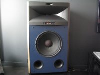
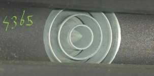
Another classic horn in JBL's 4367 predecessor, the 4365.
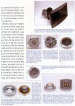
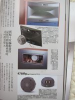
The compression driver attached to the mid/high horn is the 476Mg, with Magnesium Alloy diaphragm, instead of Beryllium (476Be).
A close up reveals the rapid-flare, coherent-wave, four-slot phase plug.
The compression driver attached to the mid/high horn is the 476Mg, with Magnesium Alloy diaphragm, instead of Beryllium (476Be).
A close up reveals the rapid-flare, coherent-wave, four-slot phase plug.
Attachments
Last edited:
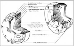
How do you know it is coherent-wave? What do you mean by that?...A close up reveals the rapid-flare, coherent-wave, four-slot phase plug.
How do you know it is coherent-wave? What do you mean by that?
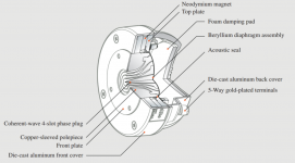
That's what JBL wrote in the docs apparently, you can decipher it's written this on the cut drawing (fourth picture) 😉
Attached, a better drawing of the 476.
From the front, the plug of the ancient 2445 doesn't look much different.
From the front, the plug of the ancient 2445 doesn't look much different.
Attachments

Last edited:
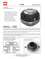
As regards the BMS 4590, some comments:
The way you can think about it is physical wavelength sizes. When the circumference of the pathway is equal to or smaller than the wavelength passing through the pathway, its dispersion is controlled by the pathway shape. When the pathway is acoustically large in comparison to the wavelength, pattern control is set and the horn you attach has little to no effect. The higher frequencies are just beaming through the acoustically large pathway. If the crossover is set to 6KHz, when the internal cross sectional area increases to 2.596cm^2 the dispersion pattern is set. For the BMS coaxial this means the high frequency pattern is set well within the driver, or available pattern. If it is to go on a 40º horn it would use less than the available pattern.
Additionally, the 4592 has a wider exit angle than the 4590.
The 4594 is shorter, and has an even wider exit angle. So its available HF distribution angle is bigger.
The 4590 is not partitioned, both the super-tweeter ring and the mid-tweeter ring use the same phase-path system, which means both mids and highs go through both tubes.
This is on the 4590 only. The 4592, 4594, 4595 have a single, not partitioned path to travel through.
Tom Danley:
"Everyone who has looked at making a bass horn has seen the reference to the ideal mouth size, a daunting 1wl in circumference. If you look at the acoustic radiation resistance curve for a radiator / horn, you see that that point is approximately where the curve goes from slanted up to flat.
This curve has Frequency on the horizontal and resistance on the vertical. The “impedance transformation” part of a horn is the coupling of the large end where the resistance is greatest, to the small end which has very little loading. If one makes the horn mouth that ideal size, one has insured that at any frequency above that, it will always present a constant load (the flat part of the radiation resistance curve). Also, making the horn much larger, has no further effect on loading but can control directivity.
It follows then that at 20KHz where the wavelength is only 5/8 inch, that ALL of the impedance transformation takes place well before reaching even a 1 inch exit.
In a wide band horn, one can picture that the active portion is the entire length at the low cutoff but the “active” region moves towards the compression as the frequency climbs.
Past the active (impedance transformation) portion of the horn is a part where the horn is still confining the radiation angle. Once one is in that region, if you change the horn wall angle or have a discontinuity, it is possible to radiate from that location like with edge diffraction etc. Earl Geddes waveguides are a case where the horn wall angle is changed at a precise rate which avoids that problem.
As you move closer to the horn mouth, you reach a dimension large enough relative to the frequency where the wave can be “launched” free form the horn but still maintain that shape. Don Keele discovered this and through several of his papers (beginning with “what’s so scared about exponential horns) arrived at the “pattern loss frequency” thumb rule. Given the dimensions, the frequency and horn wall angle, one can find the frequency down to which that horn angle will maintain that radiation angle.
So in addition to the acoustic transformation region moving towards the driver as the frequency climbs, so does the pattern control point.
This is why an exponential (normal curved wall horn) has a narrowing radiation angle with increasing frequency.
Also, what you want to avoid is doing anything to the wave front, once it is large enough to have it’s own directivity because that can easily cause a secondary radiation from that point and radiation from more than one point (points more than ¼ wl apart), this produces an interference pattern.
To “fill” out a horn, you do not want a source which already defines the radiation angle, that is what you want the horn to do. So, one can consider how the driver radiates as a simple source before adding the horn to it to make sure that it is the horn, not the driver that is defining the pattern.
On the BMS drivers (Hi Jack), I like these a lot because many radiate an expanding wavefront into the conical horns I use. This makes the acoustic path more like a continuous horn down to a small dimension and then what radiates is as much like a spherical patch as possible. They have other advantages in output and an usually low resonant frequency (more like a TAD) which makes the Synergy crossover easier into 5 in mids.
I use the 1.4 inch coax drivers too, they are really powerful but to be clear, they are projecting a well defined beam at 20Khz due to the dimensions and configuration and it is difficult to make the same phase shift free Synergy horn xover passively. That aside, it is a really powerful and good sounding driver."
However, to my knowledge Danley doesn't use the 4590 in any of their products.
Attachments
Last edited:
Wow, many thanks for the documented input 🙂
The game is about to find a good one enough not being the TAD. But with same good band width (2 ways friendly).
The game is about to find a good one enough not being the TAD. But with same good band width (2 ways friendly).
The TADs are overrated IMO. It's not that these aren't good, but I don't like to buy obscenely expensive stuff when reasonably priced alternatives are available.
There's one particular driver I have a bead on. It's supposed to be superior to nearly all highly regarded large format drivers (including the Radian 950 Be PB) and should even outperform some of the best 1" drivers in the top octave. There's one potential caveat; the phase plug doesn't end at the exit. IOW, it's got a conical exit section 😱
Anyway, here are the TADs, from left to right: TD-2001, TD-4001, TD-4002, TD-4003.
Attachments
Last edited:
Anyway, here are the TADs, from left to right: TD-2001, TD-4001, TD-4002, TD-4003.
The first drawing is of the TD-2002, attached is the correct drawing of the TD-2001 as well as a TAD TD-2002 with an Aluminium 'Spherical Wave' horn.
Attachments
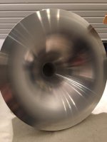
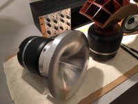
The first drawing is of the TD-2002, attached is the correct drawing of the TD-2001 as well as a TAD TD-2002 with an Aluminium 'Spherical Wave' horn.
I dedicate this song to these TAD drivers, maybe even I would marry them 😛

YouTube
Sorry for offtopic, guys 😀
P.S.
btw friend of mine has compared third harmonic in tad 2002 (with custom horn) with that in vifa pl27tg35 for the same SPL. These drivers are just wonderful !

Last edited:
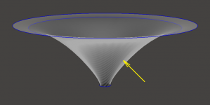
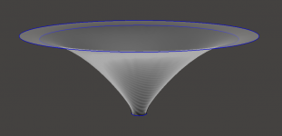
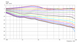
If one is willing to 1) go non-axisymmetric and 2) tolerate the slightly non-axisymmetric radiation pattern, it is possible to increase the throat impedance a bit by making the vertical coverage a little narrower.
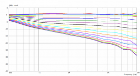
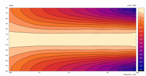
This is the comparison of two such waveguides (the bigger is the one from #2333). The smaller one has a slightly narrower nominal vertical coverage. The mouth is circular in both cases.
Horizontally (basically the same):

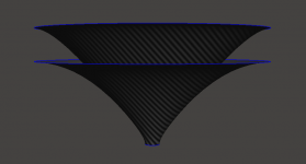
Vertically (the yellow arrow indicates a boundary of the narrower one):

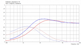
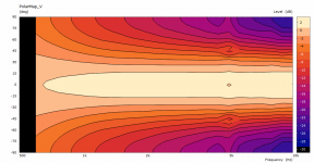
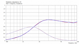
And the impedances (blue = the smaller one, with narrowed vertical):

This is the comparison of two such waveguides (the bigger is the one from #2333). The smaller one has a slightly narrower nominal vertical coverage. The mouth is circular in both cases.
Horizontally (basically the same):
Vertically (the yellow arrow indicates a boundary of the narrower one):
And the impedances (blue = the smaller one, with narrowed vertical):
Attachments
Last edited:
Has he tried also some other compression drivers? 🙂btw friend of mine has compared third harmonic in tad 2002 (with custom horn) with that in vifa pl27tg35 for the same SPL. These drivers are just wonderful !
Has he tried also some other compression drivers? 🙂
Actually I don't know 🙂.
From what I have measured personally, I would highlight Meyer Sound MS-2010. They had distortions even less than 18Sound with beryllium membrane. 🙂.

Last edited:
As we wrote up in AES many years ago, THD in a compression driver is not something that has an audible effect. Subjects could not tell the difference between 5% and 25% THD in a couple of compression drivers. It is simply not an important factor.
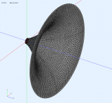
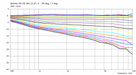
Out of curiosity I took the OS waveguide from #2333, kept the overal diameter and nominal coverage but decreased the round-over "radius" (so the length had to be increased):

The original one:

The longer one:

The impedances are virtually the same, probably as expected.
The original one:
The longer one:
The impedances are virtually the same, probably as expected.
Attachments
Last edited:
As we wrote up in AES many years ago, THD in a compression driver is not something that has an audible effect. Subjects could not tell the difference between 5% and 25% THD in a couple of compression drivers. It is simply not an important factor.
Dear Earl, I know that AES paper. To what extent did you equalize the frequency responses of the tested drivers ?
- Home
- Loudspeakers
- Multi-Way
- Acoustic Horn Design – The Easy Way (Ath4)