Will do agdr.
Some mechanical to consider. Move everything that is supposed to be screwed on the front closer to the edge! Make the input swich hole smaller or find a fatter button. Make the hole for the 3,5mm output similar to the 3,5mm input as on my frontpanel the use I had of the bolt was that it restricted sideways movement. Recommend not to solder anything unless the builder has the front and back in their hands or sturdy templates. The input could be saved by a sleeve disminishind the hole (that is to big) as it would hide the "parts" 🙂.
So far still 39,2 centigrades.
Regards
Will do agdr.
Some mechanical to consider. Move everything that is supposed to be screwed on the front closer to the edge! Make the input swich hole smaller or find a fatter button. Make the hole for the 3,5mm output similar to the 3,5mm input as on my frontpanel the use I had of the bolt was that it restricted sideways movement. Recommend not to solder anything unless the builder has the front and back in their hands or sturdy templates. The input could be saved by a sleeve disminishind the hole (that is to big) as it would hide the "parts" 🙂.
So far still 39,2 centigrades.
Regards
Thanks for the feedback! That gain switch is one thing I have on the list to modify if I ever do another version. Ideally it should come forward on the PC board a few mm. As it sits right now I've had to make the hole around it that large to make sure the top of the button doesn't get trapped behind the panel. With the switch forward about 2mm that wouldn't happen and the hole can be smaller, like around the gain switch on the O2.
The hole around the 3.5mm output jack is big on purpose to make sure the metal nose of the jack doesn't touch the panel. 🙂 I just wanted to make sure the panel was single-point grounded at the input jack only. Since I designed the ODA a new vertical 3.5mm jack has come out with a plastic nose, which would solve the problem. Then that hole coule be made smaller. That jack has a different PCB hole pattern though and wouldn't fit on the existing board. The Neutrik 1/4" jack already has a plastic nose.
39.2 C sounds about right! 🙂
Hello AGDR!
I'm examining data sheet of the NJM4556 but the gain/phase look quite odd, it has only 40db gain and the gain plot cross the x axis at 4MHZ but the NJM4556 has GBW of 8MHZ according to the datasheet, can you explain it for me?

I'm examining data sheet of the NJM4556 but the gain/phase look quite odd, it has only 40db gain and the gain plot cross the x axis at 4MHZ but the NJM4556 has GBW of 8MHZ according to the datasheet, can you explain it for me?
Hello AGDR!
I'm examining data sheet of the NJM4556 but the gain/phase look quite odd, it has only 40db gain and the gain plot cross the x axis at 4MHZ but the NJM4556 has GBW of 8MHZ according to the datasheet, can you explain it for me?
It is the difference between open loop gain and closed loop gain. 🙂 The GBW is taken from an open loop gain graph, but that graph NJR publishes is for a non-inverting stage set up with feedback resistors to get 40dB (=100x voltage gain) of closed loop gain.
Here is the story from NJR:
The chart of "Voltage gain vs. phase frequency characteristics" shows all 40dB gain. Doesn't it also explain voltage gain Av figures | Product FAQs | Design & Support | Semiconductor | New Japan Radio(New JRC)
This is why the maximum gain appears to be low at 40dB.
Turbon, looks great! I too like the silver with the red lettering. And really like the look of the vent holes in the back panel over the squarish ones... much sleeker.
Enjoy your new "toy". The only problem is everything else you have will start sounding like crap compared to ODA 🙂
Enjoy your new "toy". The only problem is everything else you have will start sounding like crap compared to ODA 🙂
Random idea that just popped into my head:
Has anyone tried the '4556A in the standard O2's gain stage?
I expect it'll be quite well-behaved (including at high gains) without reaching quite the same high-frequency performance as a '5532 due to noticeably lower slew rate (and not sure about common-mode effects), so in the end you may just end up going with the latter part of similar current consumption... I imagine the difference may depend on which manufacturer's 5532 you're using though.
Guess I should finally get a good recording soundcard again, an O2 and a bunch of opamps. Measuring stuff is just too much fun... 😎
sgrossklass - good idea! I don't think I've ever heard of anyone trying swapping a NJM4556A in for the NJM2068, at least not for anything more than a few seconds during troubleshooting to test if a NJM2068 is good or not. Never had occured to me either, but that is a great idea. The pinout is the same. The output DC offset might be higher, but doesn't matter since the first stage is capacitor-coupled to the second in the O2.
With the NJM4556A in there it would have no trouble powering a 5K pot, instead of the 10K in the stock O2, plus that 1.5K feedback resistor on each channel as you noted! The NJM4556A should certainly struggle less with large signals. There is a 4.7uF film cap available that is the same form factor as the 2.2uF coupling cap in the O2 so the frequency response could be kept the same with a 5K pot (the ground return resistors on the output stage's input can drop from 40.2K to 24.9K too).
From what I can remember of all NwAvGuy's writing on his blog and the various posts and comments, he liked the NJM2068 because it was low noise - and cheap. But that was also back in the day when he was thinking that 6.5x voltage gain was a good idea. The reality now is that most folks run their O2's at 1x - 2.5x. Whatever noise exists wouldn't get amped up much.
Hey before investing in a soundcard, consider the QA405 that may be out in the next few months: https://www.quantasylum.com/content/Home/tabid/40/EntryId/33/QA405.aspx . (scroll down). I have the QA400 which is just a soundcard in a dedicated box with custom software and calibration ability. The thing is great, but this 405 should top it by quite a bit.
Last edited:
Right, with knobs and burnt in for 100h. Listened again for the same material as I have done through the build. Masakela - Hope - wav, Thin Lizzy - Johnny the Fox, Albinoni - Oboe concert no 9 (this time through mine HD-650's). There is really nothing to say - perfect in my ears - as "objective" as the O2 but it has that extra punch where the O2 was weak to my ears. Then again I said the same about the O2... Will I gain from further upgrades at 55? Shouldn't we strive for a parametric volumecontrol or equalizer if you wish. Hearing is to decline - just let it come but lets fight it! Well known speakers or headphones is a good start so pick yer favourite and start ask if it could be implemented! Keep the pressure high! 😉 Enough about that 🙂
Feels stronger - more powerfull... More juice or what you want.
Oh, yes, the nut screewed to the 3.5mm output havent spooked yet... I will use the lathe to create a plastic insert as I probably would do to the flimsy volume and gain rods not to speak about the gain switch 😉 ...
Highly recommended!
Oh yes - the picture 🙂
Brgds
Feels stronger - more powerfull... More juice or what you want.
Oh, yes, the nut screewed to the 3.5mm output havent spooked yet... I will use the lathe to create a plastic insert as I probably would do to the flimsy volume and gain rods not to speak about the gain switch 😉 ...
Highly recommended!
Oh yes - the picture 🙂
An externally hosted image should be here but it was not working when we last tested it.
Brgds
Last edited:
Then again, a parametric signature is probably most usable on headphones or when you are listening by yerself as it would probably sound as sh*t to the fellow man without the exact problem one have.
So a switch for this please 🙂
Regards
So a switch for this please 🙂
Regards
Last edited:
Oh, yes, the nut screewed to the 3.5mm output havent spooked yet... I will use the lathe to create a plastic insert as I probably would do to the flimsy volume and gain rods not to speak about the gain switch 😉 ...
Thanks for the feedback and review! 🙂 I do like how that silver case came out. 😀
Yeah the plastic insert would be a good way to go. I have the output and input sections on different star ground segments. If the output jack touches the panel it will bypass the star grounding. It won't damage anything if the output jack touches, but you will get your very best audio quality if it doesn't.
I will keep an equalizer in mind for a future project. 🙂
Listened for over a month now with different inputs and a variety of music. I do not want to know IF it can be bettered 🙂. This is good enough for me... Other projects are calling. Thanks for your just perfect support and all help you have provided agdr 🙂
Regards
Regards
Turbon - thank you for the feedback! I'm pretty happy with how this amplifier has turned out. 🙂
It has been a couple months since I last posted and my ODA is still going as strong as ever. But my DIY itch is really starting to bug me again 🙂 I am doing everything in my power to not build another O2 (the new inverting one agdr released recently)
So my main focus is to get back to completing my desktop system with the ODA. My first idea was just to use the ODA as a pre-amp and plug it into a couple active monitors, but now after trolling these forums, my "crazy" idea is to build some small speakers and power them with the ODA.
Before you think that I am delusional, check out this youtube video of someone using the ODA to power 15" JBLs https://www.youtube.com/watch?v=VTbWVEKzVpY
I'm not trying to power anything this large... Fostex makes a 3" full range speaker with a 5W rated input at 8 ohms. With 86.5 dB/mW sensitivity, I have no doubts the ODA will have enough power. My concern is the impedance. (Speaker model is Fostex FF85WK)
The last thing I want to do is damage my amp. So what, if any, are the risks of using the ODA to power some small speakers with only an 8 ohm independence? I'm pretty confident the enclosure can dissipate the heat, but can the chips take the increased current draw?
If your thinking of building an Inverting version contact AGDR via PM, he only has a few boards left and I dont think he is going to order any more....letting it become a true DIY.
Alex
Alex
But my DIY itch is really starting to bug me again 🙂
The Force beckons... "build another headphone amp, Luke" 😀 (I saw the new Star Wars today).
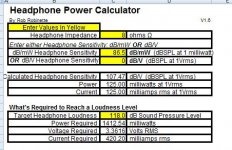
You should be OK with driving the 8 ohms speakers at 86.5dB/mW with the ODA, IF you used the +/12Vdc power rails instead of the +/-15Vdc (I can't remember, I think you built with +/-12V). From the spreadsheet below even a blasting-loud 118dB SPL would be OK, at least on peaks. That is 420mA output, so divide by 6 (3 dual chips per channel) and you get 70mA, same as what NwAvGuy used as his maximum per-opamp number for those NJM4556A's. You will also need the full 2.4A WAU16-2400 power transformer in the BOM, if you don't already have that one.
In actual measurements the NJJM4556A's are good up to 90mA before they current limit. But the limitation here comes in package power dissipation. The SIP8 package in the ODA has the extra 100mW of dissipation, 800mW vs. the 700mW for the DIP chips in the O2. The quiescent (idle) current with the +/-12Vdc power ralls consumes about 40% of that available package power dissipation just sitting there, as I recall from the math, so that remaining 480mW per chip is what's left to play with for the audio power dissipation.
With normal average listening levels of 90dB or so, with the occasional peak up over 110dB. you should be just fine powering those small speakers.
And... you will still have low distortion, better than the O2 amp! Thinking back to that one set of dScope tests that Mike G. did on the ODA, as I recall. He was able to go all the way up to 400mA per channel (might have been 380mA, can't remember) at THD levels slightly below what NwAvGuy reported (NwAvGuy could only go to 140mA of course with the O2's single NJM4556A chip, and his THD low only to 120mA or so before shooting up) before the THD shot up.
Yep, Alex is right about the inverting O2 PC boards. In the spirit of what NwAvGuy did with his O2 headamp I'm not making any profit of off the inverting O2 version. 🙂 The boards I have now from this last small run are at-cost for anyone who is a member of the forum here, plus actual shipping. I'm not going to stock any of the PC boards for sale at the website once these are gone, but keep in mind I have posted the Gerber files here on the forum and at the Google Drive project link. Anyone can have their own PC boards made for DIY use. I'm also not selling assembled units, partially assembled boards etc. for this one. If someone wants an inverting O2 they either have to build it themselves, or do a deal with another DIY'er. 🙂 I've purposely kept 95% of it through-hole, in the spirit of what NwAvGuy did wiht his O2, to keep it easy to DIY.
However I do have a bunch of the LME49880 chips and that red clipping LED, the same one used on the O2, which are used on the inverting O2 board and are both discontinued parts now. If anyone building an inverting O2 needs them just send me a PM. They are yours at actual cost plus actual shipping cost. Like I posted in the Inverting O2 thread, the best substitute chip for the LME49880 is probably the NJM MUSES 8920 FET-input chip (Mouser # 513-MUSES8920E), which goes for about $12 each on Mouser. It is supposed to be their higher-end version of the NJM2068 gain chip used in NwAvGuy's O2, so it would be a fitting chip here, keeping in the spirit of the O2. The NJM2068 in the O2 is bipolar input though, while I specifically used the FET-input LME49880 (or this FET-input MUSES 8920E) in the inverting version. In addition to the lower common mode distortion inverting op-amp configuration, I've been wanting to try FET input chips in an O2 version. 🙂 The OPA2140 looped with the BUF634 output buffers is also FET input.
Attachments
Last edited:
I wa thinking of wiring up these to the ODA and see how they play!!!
Model:SongTower QWT
Design MTM 2-way Quarter Wave Tube Transmission Line
Drivers (1) Hiquphon OW2 tweeter , (2) Seas ER15RLY midwoofers
Response 42Hz - 20KHz (+/- 3db)
Sensitivity
(dB/2.83v/1M) 88db
Impedance 4 ohms nominal
6 ohms average
Recommended Amplification 30 - 150 tube watts
80 -250 solid state watts
Box Alignment Quarter-wave transmission line
Weight 49 pounds each
(not including plinths and spikes)
Dimensions
(HWD) 44.5" H x 8" W x 12" D
(not including plinths and spikes)
4 Ohm design but 6 ohm average!
Alex
Last edited:
Erm... The ODA was measured to deliver about 1.68 W into 16 ohms, presumably current-limited. That should translate to about 630 mW into 6 Ohms, maybe a bit more so. Let's be generous and assume 800 mW. That's little more than 85 dB / 1m tops, and assuming about 10-14 dB of crest factor, 71-75 dB average.
This would be quite adequate for me, being a generally quiet listener with a preference for nearfield, but party level it is not.
Sure they say the first watt is important, but an amplifier with no more than the first watt, I don't know - that's like portable radio level...
You can try it, of course, but it would seem to be about as effective as using a big truck on a F1 racetrack. Horses for courses and stuff.
Hi guys! 🙂
Alex - I would agree with sgrossklass here, those 4/6 ohms speakers wouldn't work out well.
Here is a good way to think about it all. NwAvGuy's O2 will work with any 32 ohm headphone, regardless of sensitivity or music volume. It will only work with some 16 ohm headphones though (even though his write-up claim it will work with all 16R, that isn't correct, there have been several cracked-in-half NJM4556A chips over the years). Most anything below 16 ohms won't work with the O2, with results ranging from significant/severe distortion and/or the two NJM4556A chips cracking in half from overheating.
I say "most" here because I believe there is a tiny "island" in the THD curves where 8 ohms with very high sensitivity and low music volumes and peaks would work with NwAvGuy's O2, but like sgrossklass says that kind of situation really isn't usable.
Here, with this "ODA" version, the impedance it can drive goes down one notch. 🙂 It can drive any 16 ohm headphone, regardless of sensitivity or music levels. But it can only drive some 8 ohm "things" - speakers and headphones. There probably is such a thing as an 8 ohm headphone, indirectly anyway, in the "chargers" for electrostatic headphones which are designed to hook to the speaker outs of speaker amps. But most anything below 8 ohms won't work well at all with the ODA, with results again ranging from significant distortion to cooked output chips.
Hey while I'm posting in this thread I should say that I probably still have a bare ODA PC board or two if anyone out there is still thinking about building one. Same deal, at-cost whatever that was (I would have to go back in the thread and look) plus actual shipping. The ODA board has a large amount of "larger" 1206 sized surface mount parts. If you don't have much surface mount soldering experience you will by the time you are done. 🙂 The ODA uses the now-obsolete LME49990 chips, but I have a bunch of those too I'll sell at-cost for anyone building an ODA.
Last edited:
- Home
- Amplifiers
- Headphone Systems
- A version of an O2 Desktop Amp (ODA)