Well that puts that experiment to bed!!!
Cracked chips I think not!! LOL.
I will leave those towers to my Van Alstine Ultravalve amp!!
Gosh I would think someone out there would grab that ODA board its a very very good amp.
Alex
Cracked chips I think not!! LOL.
I will leave those towers to my Van Alstine Ultravalve amp!!
Gosh I would think someone out there would grab that ODA board its a very very good amp.
Alex
IF you used the +/12Vdc power rails instead of the +/-15Vdc (I can't remember, I think you built with +/-12V). You will also need the full 2.4A WAU16-2400 power transformer in the BOM, if you don't already have that one.
Check and check. This is really starting to sound promising, so I'm going to try it. I had to special order some wood for the boxes, so I have a good 2 week wait on that. But when done, I'll post results in case anyone else wants to try with their ODA.
What if F150's 8 ohm speakers aren't 8 ohms over the entire frequency spectrum? Would he have to be concerned with the average impedance?
Alex
Alex
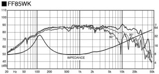
Here is the frequency response for the speakers I am thinking on using. (I haven't purchased them yet)
My main focus was on the 3" model FF85WK, but there is also a 4" FF105WK. The 3" seems like a perfect fit being as it's rated for 5W. The 4" is rated for 10W, but it is more efficient at 88dB/W vs 86.5dB/W on the 3".
Both are more than 8 ohm on average looking at the curves and both of these speakers get really good reviews on this forum in the full-range section. I might go with the 4" model to get more low end, but it will be under driven based on the specs.... decisions, decisions.
(I hope this isn't too off topic for this thread)
Attachments
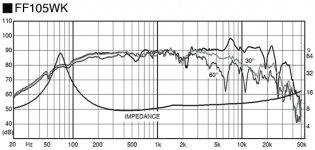
Well they both seem not to dip below 8 ohms so you may be ok. As AGDR just posted some 8 ohms are ok....and the more efficient driver may indeed be the better choice.
I think I would have a thermocouple on hand and monitor the temps just in case....
Alex
I think I would have a thermocouple on hand and monitor the temps just in case....
Alex
Good questions about nominal speaker impedance! Thanks for posting the curves. Either of those would be just fine as 8 ohms seems to be the minimum. Those peaks in the curve at 70Hz and 120Hz show why having a low output impedance from the amp is so important. If an amp had several ohms of output Z those peaks would start forming a bit of a voltage divider.
But yep, in general, it is good to have a look at the impedance curve if available. Something advertised as 8 ohms nominal might actually be spending most of the time at 6 or 4 ohms. A few small dips down to 6 ohms in a speaker impedance curve wouldn't be a problem.
EDIT: hey Alex, we posted at the same time!🙂
Last edited:
Transformer case for the ODA
Why not combine the transformer red case with the ODA and the ODAC?
This way everything would be in one beautiful red case.😀
Why not combine the transformer red case with the ODA and the ODAC?
This way everything would be in one beautiful red case.😀
Yes it would!
I left the ODAC out just to be able to use it with other amps and systems....I am seriously thinking of installing a rev b in the new inverting type O2 amp and in the ODA...being retired now the budget has too stretch!! LOL!
Alex
I left the ODAC out just to be able to use it with other amps and systems....I am seriously thinking of installing a rev b in the new inverting type O2 amp and in the ODA...being retired now the budget has too stretch!! LOL!
Alex
I agree, that would look nice to have it all in one case! I really like the way louiebh's units turned out. He wrote me recently that he is using some HD800s with it now. 😀
Unfortunately the B5 case is the biggest extruded aluminum case that Box Enclosures has, at least in terms of width. I wish they did make a bigger case! They do sell longer versions of the B5 and last I looked some were even in stock at the distributors. I gave that some thought at the time with louiebh's build, using the "two board" option with a second ODA board in the back with just the power supply parts populated. Then try mounting a toroid on the front part of that rear board.
But I couldn't find a toroid that would fit in the space between the top of the board and the top of the case. His location uses 50Hz so the transformers are a bit larger. There is also always the concern of having the transformer near the audio signal lines (the rear RCA jacks). In the end I figured the easiest build would be with the toroid in the separate box, plus it puts lots of physical space between the transformer and the audio signal section.
I believe that I put mounting holes in the corners of the ODA board though, thanks to a good suggestion that was posted. So it would be possible to just standoff-mount the ODA in a larger case with a transformer. The front panel stuff could be wired out to panel mount parts - jacks, pot, switches, etc. It would be a lot of work but it would certainly look nice!
Alex - you should definitely get a revB ODAC and mount it in there. 🙂 I can't remember if I sent one of the top-slot ODAC carrier boards. If not please send me a PM.
Texas Instruments is dropping chips
The Texas Instruments LME49990 and LME49610 chips are at End-Of-Life.
It's difficult to obtain these chips at a reasonable DIY price. Is there a
substitute chips for each? Will they work with the present set of PCB's?
I would hate to see "A version of an O3 Desktop Amp (ODA)" disappear from the DIY Community.😡 Any ideas and plans would be vital to continue the development of this great desktop headphone amp. I have 4 ODA PCB's
that I just started to build. Where can I get some LME49990 and the other
chips needed for this Amp.😕
I always hate when a company stops making a set of great chips.
Does Texas Instruments have drop in replacements for these two chips?😕
What we need is information. Take care.
Last edited:
Hi mrsavage!
I have a bunch of the LME49990's here I'll sell at-cost to anyone building an ODA. I did a big buy when I heard the news they were being discontinued. I believe that theAnonymousOne on the forum here posted once that he bought a couple of hundred from Arrow, if I'm remembering right, when the news from TI hit. He might be another one to contact. 🙂
Having those LME49990s discontinued will affect opc's "Wire" headamps too - they are LME49990 + LME49600. His UPLHP uses the LME49610s, which were also discontinued. TI's decision really screwed up the DIY audio community. 😡 From what I read the particular National Semi fab line in Scotland became obsolete and TI had no interest in re-tooling the chips to work on a more modern fab line. The LME49990s were terrific chips, as opc's posted AP measurements a couple of years ago showed.
The ODA amp here uses the NJM4556A SIP form-factor chip for the buffer chips. Those are still in stock and being sold at mouser. So for the ODA it is just those LME49990s that are being discontinued.
As for the LME49600s, there is a DPAK (TO-263) version of the BUF634 chip that may be equivalent. I'm using the T0-220 version of the BUF634's now in the inverting O2 project with good results so far. Current buffer chips tend to reflect much of the properties of whatever chip they are looped with anyway, so LME49600 vs. BUF634 might wind up not making all that much difference.
One or two of the other parts in the ODA might be discontinued now, but if so I have them here. Just send me a PM if you run into any. 🙂 One is that power switch. I have the original Mountain Switch types I specified, but I've since found out that C&K makes and exact replacement that is in stock at Mouser. I've been meaning to add a note about that to the BOM.
Last edited:
My twisted pair wires were bus wire with shrink tubing. A bit lower gauge than what I suspect is recommended. Would this lower the volume a bit? I'm also thinking of going back and changing the attentuation resistors to raise the gain stepping a bit.
You can see the wires in my post here: http://www.diyaudio.com/forums/head...ersion-o2-desktop-amp-oda-81.html#post4340404
You can see the wires in my post here: http://www.diyaudio.com/forums/head...ersion-o2-desktop-amp-oda-81.html#post4340404
Last edited:
Hi allindaze!
The link isn't going to the right post for me, but I'll bet is the photo on post #802. Small guage wires are OK for the twisted pair feeding the pre-amp section. There isn't much current going through them. Your wiring there is OK. Also those wires only affect the pre-amp output, they won't have any effect at all on the amp output via the front panel 1/4" or 3.5mm jacks.
What size wire did you use for the power supply in the rear? Those two should be 22 AWG or greater. I can't quite tell from the photo if that is bigger wire than the twisted pair up front or not.
Please let me know what models of headphones you are using and I'll feed them into a spreadsheet to figure out the voltage needed.
With the attenuation resistors in place (R31 & R32) the lowest gain position is actually 1/2x, 50% attenuation rather than voltage gain. I have it set up the way, as the BOM default, for sources with high levels coupled with headphones with high sensitivity, which is the case with most of my sources and headphones.
But in your case you may have sources with more normal-to-low levels and/or headphones with lower sensitivity levels. In that case the first - and easiest - thing to do is just jumper (short) each attenuation resistor straight across on the bottom of the PC board. So just solder a shorting wire across the pins of R31 under the board, then another across R32. No need to even remove the two resistors. That will change the lowest gain switch setting from 1/2x to 1x and double the maximum volume (and output voltage swing) in ALL the gain switch settings.
Last edited:
Hey, i didn't have time to read the whole thread. But i'm in the market for a new amp dac combo, and the o2/odac looked really interesting. But i will use it as a desktop amp and nothing else. But having all the ports in the front and wasting lots of space to fit the 2 9v in it makes no sense.
But is there a actually desktop amp kit for the o2? or should i be looking elsewhere for a desktop amp?
But is there a actually desktop amp kit for the o2? or should i be looking elsewhere for a desktop amp?
But is there a actually desktop amp kit for the o2? or should i be looking elsewhere for a desktop amp?
In your area Head 'n' HiFi in Switzerland has what you are looking for:
O2 Headphone Amplifier Desktop Kit
Desktop Headphone Amplifiers
and he is on the forum here too:
Head 'n' HiFi - Walter - diyAudio
Also - shameless self promotion 😀 - you might want to take a look at my "inverting O2 headphone amplifier" project here on the forum:
http://www.diyaudio.com/forums/head...avguy-o2-headphone-amp-vs-original-thd-n.html
That one is desktop-only and also has a place for an ODAC inside. 1/4" and 3.5" output jacks on the front panel for the headphones, RCA outs for the DAC in back, gain switch like the O2, and a few "improvements" IMHO on things about the O2 that have been bugging me over the years. Like having the power jack in back, LDO voltage regulators heat sinked to the case, input select switch, etc. It also has a higher power supply voltage (+/-15.3V vs +/-12v) than the O2 and higher output current, so it is compatible with a wider range of headphones and IEMs than the O2.
It is the same over-all concept of the O2 with a gain stage in front, pot in the middle, and output stage, but a bit different in that the amplifiers are in the less common inverting configuration. The amp uses FET-input chips vs. the bipolar input in the O2. The project is about 95% through-hole parts for easy soldering. The 3 chips and some capacitors on the back of the board are surface mount. My ODA amp in this thread is mostly surface mount parts, more of an advanced build, at least in terms of soldering skill.
Congratulations on joining the audio hobby! If you are like the rest of us you will have a shelf-full of headphones and amps in no time at all. 🙂
Last edited:
The wires are pretty thick, almost too thick. I have some 30 gauge wiring which I could replace them with but that is almost too thin.Hi allindaze!
The link isn't going to the right post for me, but I'll bet is the photo on post #802. Small guage wires are OK for the twisted pair feeding the pre-amp section. There isn't much current going through them. Your wiring there is OK. Also those wires only affect the pre-amp output, they won't have any effect at all on the amp output via the front panel 1/4" or 3.5mm jacks.
What size wire did you use for the power supply in the rear? Those two should be 22 AWG or greater. I can't quite tell from the photo if that is bigger wire than the twisted pair up front or not.
Please let me know what models of headphones you are using and I'll feed them into a spreadsheet to figure out the voltage needed.
With the attenuation resistors in place (R31 & R32) the lowest gain position is actually 1/2x, 50% attenuation rather than voltage gain. I have it set up the way, as the BOM default, for sources with high levels coupled with headphones with high sensitivity, which is the case with most of my sources and headphones.
But in your case you may have sources with more normal-to-low levels and/or headphones with lower sensitivity levels. In that case the first - and easiest - thing to do is just jumper (short) each attenuation resistor straight across on the bottom of the PC board. So just solder a shorting wire across the pins of R31 under the board, then another across R32. No need to even remove the two resistors. That will change the lowest gain switch setting from 1/2x to 1x and double the maximum volume (and output voltage swing) in ALL the gain switch settings.
I have the Massdrop edition AKG K7XX which I usually need to have the gain switch cranked to the 5th position for. I'll take a look at which resistors I installed and solder a bridge on the underside like you recommended. Thanks for the response. If I have any questions I'll give you a shout.
I have the Massdrop edition AKG K7XX which I usually need to have the gain switch cranked to the 5th position for. I'll take a look at which resistors I installed and solder a bridge on the underside like you recommended. .
Yep, that is likely one of the problems, you need to short those two attenuation resistors. I've attached the spreadsheet below. Here is the specification page for the Massdrop K7XXX:
https://www.massdrop.com/buy/akg-k7xx-massdrop-first-edition-headphones
The K7XXX uses the K702 drivers, which are 62 ohms and 105dB/V sensitivity. Plugging that into the spreadsheet below gives 5.63Vrms (= 8Vpeak) and 90mA(rms) required per channel to hit (super loud, but for instantaneous musical peaks) 120dB SPL.
The problem is that with the attenuation resistors installed the maximum output swing is cut in half, from 10.25Vpeak to 5.1Vpeak = 3.6Vrms. So your maximum output voltage swing right now is 2 volts less than you need. Short those two attenuation resistors across and you will get your full 10.25Vpeak=7.25Vrms maximum output swing back.
However: The 3.63Vrms maximum output swing you should be getting right now is still 115dB SPL, which is as loud as a freight train. You probalby have another problem lurking in there somewhere! Go ahead and short those resistors across and let me know how things go. If you have a DMM please check your power rail voltage readings too, JP18 to ground (JP6) and JP19 to ground.
And those connection wires you used are OK too. 🙂
Attachments

Last edited:
Yep, that is likely one of the problems, you need to short those two attenuation resistors. I've attached the spreadsheet below. Here is the specification page for the Massdrop K7XXX:
https://www.massdrop.com/buy/akg-k7xx-massdrop-first-edition-headphones
The K7XXX uses the K702 drivers, which are 62 ohms and 105dB/V sensitivity. Plugging that into the spreadsheet below gives 5.63Vrms (= 8Vpeak) and 90mA(rms) required per channel to hit (super loud, but for instantaneous musical peaks) 120dB SPL.
The problem is that with the attenuation resistors installed the maximum output swing is cut in half, from 10.25Vpeak to 5.1Vpeak = 3.6Vrms. So your maximum output voltage swing right now is 2 volts less than you need. Short those two attenuation resistors across and you will get your full 10.25Vpeak=7.25Vrms maximum output swing back.
However: The 3.63Vrms maximum output swing you should be getting right now is still 115dB SPL, which is as loud as a freight train. You probalby have another problem lurking in there somewhere! Go ahead and short those resistors across and let me know how things go. If you have a DMM please check your power rail voltage readings too, JP18 to ground (JP6) and JP19 to ground.
And those connection wires you used are OK too. 🙂
So just to be clear with the gain position at the 3rd step and the volume at max the amp will push enough power through my headphones to blow my head off.
 The only reason I was asking about shorting the attenuation resistors is because I wanted to keep the gain and volume knobs low while keeping my computer's volume at the same level I use to listen to my music on my speakers. (I have powered speakers plugged into the amps pre-amp outputs)
This is the reason it's been so many months and I havent had any reason to bring it up. Everything is working great and the sound is wonderful I just wanted to step the headphones down from the max gain and use the volume knob instead.
I've installed the jumpers just now and am reassembling the unit. I'll let younknow how the headphones sound after everythings tighted back up.
Although I feel like maybe I should keep it open because I've been wanting to install your plate and slap the ODAC in this puppy sometime in the near future. 🙂
Last edited:
So just to be clear with the gain position at the 3rd step and the volume at max the amp will push enough power through my headphones to blow my head off.
That is right! 😀
Hmmm... but I'm making the assumption that your source level is in the 1Vrms to 2Vrms range. Could be the problem is that your incoming source level is just really low, given how you have it adjusted for the PC's speakers. If that is the case then shorting those attenuation resistors should help. They] change will 1x the input rather than 1/2x it. Please let me know the results! If low source is the problme the next thing to do would be to change the gain resistors so that instead of 1x, 2x, 3x, 4x you had 2x, 4x, ... or any custom set of gain positions you wanted.
Now that all the bugs are worked out of the ODAC with rev B I would definitely recommend adding one! Louiebh has had one in his ODA for several months and says it is working great, as per a recent email chat.
Last edited:
holy freakin moly....
WE ARE AT MAXIMUM PERFORMANCE.
I cannot explain how superb the level of sound this amp has achieved. I cannot thank you enough for building this device for us agdr. I am in absolute awe at the pure raw performance your amp is introducing into my headphones. I love it! Thank you!
Cranking this thing up to zero attenuation is leaving me dumbfounded in my music. Thank you my man!
- Home
- Amplifiers
- Headphone Systems
- A version of an O2 Desktop Amp (ODA)