Voltages on #940 diagram measure -4mV(this side tends to measure even more but starts to drop and settles to -4mV) on left side(also circled chip pin) and -0.53mV on right side.
OK, good on the measurements, now please rotate both trimpots to get the maximum output on those tests points and let me know what you get. 🙂 Thanks.
With the trimpots all the way to one side left side is now showing -5.5mV on left and right side is showing -2.31mV,
If I understood well, I must set those pots to get -2.25mV on left and -1.15mV on right side?
If I understood well, I must set those pots to get -2.25mV on left and -1.15mV on right side?
With the trimpots all the way to one side left side is now showing -5.5mV on left and right side is showing -2.31mV,
If I understood well, I must set those pots to get -2.25mV on left and -1.15mV on right side?
Mmmm.... something isn't right there. They should be pretty much the same, definitely shouldn't be off by 2.3mV I've just spotted your PM and will send you some information. Please don't solder those chips in yet! 🙂
The temporary heat sinks are only good for around 1 minute at 24Vac
An issue has popped up that I wanted to let folks building this amp know about. I'm going to be posting a revised set of build instructions later today with this information added.
The voltage regulators in my version of an ODA here heat sink to the rear panel. Getting that panel back from Front Panel Express usually takes around 3 weeks round trip though (sending them the blanks, milling time, and then they unfortunately UPS ground it back), so I've been sending a set of small temporary heat sinks with each board. Those sinks go on the two pre-regulators, the LM317 and LM337, since they dissipate nearly all the heat.
The goal of the temp heat sinks is just to get the board running long enough to make the basic measurements on the power supply, to verifiy it works, and then on the whole board to see if sound comes out. 🙂 But I've failed to emphasize that those temporary heat sinks are inadequate for continuous use - that is what the back panel is for. I would say limit the run time to around 2 minutes if using an 18Vac transformer, or just 1 minute if you are using 24Vac. Then let them cool for 20 minutes or so before doing another round of tests.
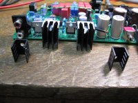
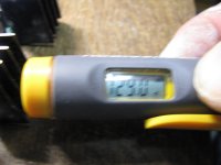
The temporary heat sinks can be beefed up for longer runtime. I'm working on a board that a fellow sent to me and I've swapped out the temporaries with some larger ones, in the photos below. With no load on the amp I'm getting 130F with these, which is stable over time. Unfortunately these particular heat sinks were from the Radio Shack stores here that went bankrupt (lol, and are doing so again with the remaining stores, I see as of today's news), so I'll have to see if I can find anything similar out there. If so I'll add it to the project BOM.
The two LT LDO final regulators don't need any heat sinks since there is only 1V across them.
An issue has popped up that I wanted to let folks building this amp know about. I'm going to be posting a revised set of build instructions later today with this information added.
The voltage regulators in my version of an ODA here heat sink to the rear panel. Getting that panel back from Front Panel Express usually takes around 3 weeks round trip though (sending them the blanks, milling time, and then they unfortunately UPS ground it back), so I've been sending a set of small temporary heat sinks with each board. Those sinks go on the two pre-regulators, the LM317 and LM337, since they dissipate nearly all the heat.
The goal of the temp heat sinks is just to get the board running long enough to make the basic measurements on the power supply, to verifiy it works, and then on the whole board to see if sound comes out. 🙂 But I've failed to emphasize that those temporary heat sinks are inadequate for continuous use - that is what the back panel is for. I would say limit the run time to around 2 minutes if using an 18Vac transformer, or just 1 minute if you are using 24Vac. Then let them cool for 20 minutes or so before doing another round of tests.
The temporary heat sinks can be beefed up for longer runtime. I'm working on a board that a fellow sent to me and I've swapped out the temporaries with some larger ones, in the photos below. With no load on the amp I'm getting 130F with these, which is stable over time. Unfortunately these particular heat sinks were from the Radio Shack stores here that went bankrupt (lol, and are doing so again with the remaining stores, I see as of today's news), so I'll have to see if I can find anything similar out there. If so I'll add it to the project BOM.
The two LT LDO final regulators don't need any heat sinks since there is only 1V across them.
Attachments
Last edited:
Radio Shack's website is still alive for the temporary heat sinks
Well look what I just found, as per the post above. 🙂 Radio Shack still has a website and they have a 50% off sale as part of bankruptcy #2. Here are those heat sinks at $1.62 each:
https://www.radioshack.com/products/to-220-to-202-heat-sink
with free ship! And while you are there they have TO-220 mounting kits with the mica and nylon washers, same thing as I have in the BOM from Mouser:
https://www.radioshack.com/products/to-220-mounting-hardware
All 4 of the regulators need to have the insulating washers installed when attaching the back panel, as per the build instructions. No need for washers though with the temporary heat sinks, just be aware that they will be "live" electrically. As per the build instructions you will have to snip the bottom few mm off the micas (cut those 2 holes off on one end) for the LT chips since they mount a bit lower.
I've just ordered a bunch of those and I'll include them with any future ODA boards for the temporaries instead of the others - but will bump it up $3 to cover. 🙂 Boards will now also come with a set of tested and matched NJM4556AL chips.
But again, these temporary heat sinks won't work for continuous use of the ODA under load. For that you need the rear panel. It looks like these will work for continuous testing use with no load though while running with an 18Vac transformer, the 130F I'm getting.
Last edited:
Normal ODA expected thermal drift and output DC offset setting
Here is some information about setting the DC output offset trimpots on the ODA, for folks building this amp. I'm been meaning to post this for awhile. I just happen to be helping with a fellow's ODA right now and took some pictures.
With the type of DC zeroing circuit in the ODA there is an expected normal amount of thermal drift as the parts heat up. I didn't use a servo on purpose, I went with an absolute voltage injection method. I have concerns (still do) about the tiny amount of AC feedback that accompanies the DC feedback with just a first order servo filter network. I had a wiki posted here once about second order DC servos but looks like it disappeared a few years with the other wikis in a database fail. those are harder to design, especially to prevent very low frequency (as in a period of minutes!) oscillation. I wanted the DC correction in the ODA to be purely DC. For this reason the DC offset trimpots should be adjusted after the ODA is warmed up for at least 30 minutes, ideally an hour.
The photos below show what is going on. This particular ODA has already had the trimpots set for minimum DC while warm. What I'm showing here is what to expect then when it is "cold" vs. when"warm":
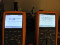
* Photo 5020 shows the output DC offset of the two ODA channels when the power is first switched on "cold". 61uV (=0.061mV) and 32uV.
* Photo 5021 is after about 2 minutes of warm up. 31uV and 22uV.
* Photo 5022 is after about 20 minutes, now 1uV and -2uV.
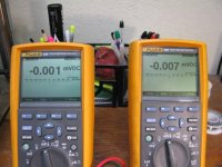
* Photo 5023 is after 2 hours, showing those final low numbers (where the trimpots were previously set) are stable in the low uV range, at -1uV and -7uV. If you click on the arrows on the lower left corner of the these photos to zoom them up you might even be able to make out the clock time in the upper left of the DMM screens.
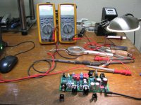
* The final photo is just the test setup, this is the same photo as the setup in post #964 above. The power transformer being used here is 18vac 1.85A.
So the amount of thermal drift in the output DC offset when going from first-switched-on cold to warm is roughly 50uV on average, which is what I've been quoting for awhile.
My goal with the DC offset in the ODA was simply a "significant reduction" from the NwAvGuy O2 headamp the ODA is based on, which typically runs at 3.6mV = 3600uV per channel. The reason is so the headphone and IEM drivers can stay closer to their natural mechanical resting position at music zero crossings, rather than 3.6mV off to one side. Rounding those final ODA measured offset numbers up to 10uV we have (3600uV-10uV)/3600uV = 99.7% reduction. I would call that significant! 😀
Here is some information about setting the DC output offset trimpots on the ODA, for folks building this amp. I'm been meaning to post this for awhile. I just happen to be helping with a fellow's ODA right now and took some pictures.
With the type of DC zeroing circuit in the ODA there is an expected normal amount of thermal drift as the parts heat up. I didn't use a servo on purpose, I went with an absolute voltage injection method. I have concerns (still do) about the tiny amount of AC feedback that accompanies the DC feedback with just a first order servo filter network. I had a wiki posted here once about second order DC servos but looks like it disappeared a few years with the other wikis in a database fail. those are harder to design, especially to prevent very low frequency (as in a period of minutes!) oscillation. I wanted the DC correction in the ODA to be purely DC. For this reason the DC offset trimpots should be adjusted after the ODA is warmed up for at least 30 minutes, ideally an hour.
The photos below show what is going on. This particular ODA has already had the trimpots set for minimum DC while warm. What I'm showing here is what to expect then when it is "cold" vs. when"warm":
* Photo 5020 shows the output DC offset of the two ODA channels when the power is first switched on "cold". 61uV (=0.061mV) and 32uV.
* Photo 5021 is after about 2 minutes of warm up. 31uV and 22uV.
* Photo 5022 is after about 20 minutes, now 1uV and -2uV.
* Photo 5023 is after 2 hours, showing those final low numbers (where the trimpots were previously set) are stable in the low uV range, at -1uV and -7uV. If you click on the arrows on the lower left corner of the these photos to zoom them up you might even be able to make out the clock time in the upper left of the DMM screens.
* The final photo is just the test setup, this is the same photo as the setup in post #964 above. The power transformer being used here is 18vac 1.85A.
So the amount of thermal drift in the output DC offset when going from first-switched-on cold to warm is roughly 50uV on average, which is what I've been quoting for awhile.
My goal with the DC offset in the ODA was simply a "significant reduction" from the NwAvGuy O2 headamp the ODA is based on, which typically runs at 3.6mV = 3600uV per channel. The reason is so the headphone and IEM drivers can stay closer to their natural mechanical resting position at music zero crossings, rather than 3.6mV off to one side. Rounding those final ODA measured offset numbers up to 10uV we have (3600uV-10uV)/3600uV = 99.7% reduction. I would call that significant! 😀
Attachments


Last edited:
I didn't use a servo on purpose, I went with an absolute voltage injection method.
What exactly is the absolute voltage injection method?
Is this the same as injecting a small DC current into the non inverting pin to help equalize input bias currents resulting in minimal offset?
Do you have a simplified schematic of it?
Thanks.
What exactly is the absolute voltage injection method?
Is this the same as injecting a small DC current into the non inverting pin to help equalize input bias currents resulting in minimal offset?
Do you have a simplified schematic of it?
Thanks.
Hi - the schematics and the rest of the project materials are at the Google Drive link in the first post in this thread. You'll want the latest V2.1 folder there.
What I'm doing is returning the ground return resistor on the input of the NJM4556A chips to a voltage rather than to ground. So on the NwAvGuy O2 headphone amp it would be the same as if the 40.2K R12 and R13 were returned to a small near-zero impedance voltage source rather than to ground. The small voltage applied to the op-amp input cancels out both the IR drop across the 40.2K resistor (caused by the op-amp input bias current) and the inherent input offset voltage of the op-amp.
Thank you for the reply.
Looking at your V2.1 schematic, it's difficult for me to follow even when blown up to full size on my 32" monitor. It still seems too small.
Can you post just the portion of the schematic showing how these ground resistors connect to a near-zero impedance source?
Is the near-zero source the same source used to power the '4556s or is it a different supply?
New relay in the BOM
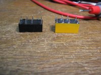
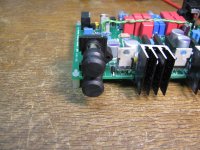
I'm changing the relay part in the BOM from the Omron G6A-234P-DC24 (Mouser #653-G6A-234P-DC24) to the Panasonic DS2E-S-DC24V (Mouser #769-DS2E-S-DC24V). The new relay is exactly the same coil current, coil resistance, and contact current rating plus it is still a sealed relay. The new relay is a little taller, though, photos below, and... yellow. 😱 The new BOM has been uploaded to the project Google Drive link.
I'm making the change because the fellow with the ODA I'm taking a look at has had some intermittent relay behavior I haven't seen in any other board. The drive circuitry is just fine after tests, so that leaves the relay itself as being intermittent. In the process I happened to be looking at a video of the internals of the HP/Agilent/Keysight 34461A DMM vs. the internals of their newer 7.5 digit 34470A DMM and noticed Agilent had swapped out those same type of Omron signal relays for the (yellow!) Panasonics. The price of the relays is similar so I'm assuming they may have found a reliability difference. If you already have an ODA there is no reason to change out the relay unless you are having relay trouble.
The new relay is a little taller but fits on the PC board just fine.
Attachments

Last edited:
Thank you for the reply.
Looking at your V2.1 schematic, it's difficult for me to follow even when blown up to full size on my 32" monitor. It still seems too small.
Can you post just the portion of the schematic showing how these ground resistors connect to a near-zero impedance source?
Is the near-zero source the same source used to power the '4556s or is it a different supply?
There is a pdf version at the link along with the png. Use the pdf, you can zoom it in a lot further, and be sure to download the PDF and use the real adobe acrobat. The Google PDF viewer doesn't zoom in nearly as far or as clearly when it does. And - I have to do this myself on the laptop screen - then use a hand magnfier if needed, but with the 32 inch you will probably be OK.
For the voltage source I'm using a filtered low-noise zener. Notice there is a T network there for the filter, it is set up to filter in both directions. What the signal will see is the 5.49K resistor in parallel with the 10R trimmer, 9.98 or so ohms, added in series with the 4.99K ground return resistor.
That 1K resistor from the trimpot wiper to ground is a safety resistor. 🙂 It has negligible effect on the circuit, 1K || 9.98R, but looking decades down the road the trimpot wiper could become intermittent with age. If it did, in this configuration, the ground return resistor would float causing the op-amp input bias current to quickly charge up the coupling caps to the rail voltage, which would then pass right through the 1x gain output stage. Having that 1K resistor there just prevents that potential disaster. Anytime I use a pot or trimpot in something I always ask myself "what will happen when the wiper eventually fails?".
Last edited:
At least 3 seconds power-off and relay circuit testing tips
Here are a couple of more ODA tips. 🙂
The ODA is completely silent turning on and off thanks to the relay circuit. Zero turn-on or turn-off thumps. HOWEVER, when doing fast power on-off cycles (during build testing) the amp needs to be "off" at least 3 seconds before turning it back on again or you could get a nasty thump. The reason is an RC delay circuit in the turn-on direction. On power down it takes at least 3 seconds for that capacitor to discharge.
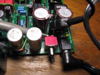
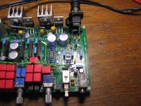
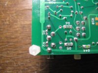
And when making voltage measurements on the relay circuit please remember that it isn't referenced to ground, and in this particular amp it isn't referenced to the (audio) negative power supply rail either. The reference point is the negative lead of the big electrolytic C8, which is the same point as the exposed (top, anode) lead of the tombstone-mounted rectifier D2. That lead makes an easy place to connect. You could also just temporarily solder a small wire to that point to bring the "relay circuit ground" off the board for easy connection.
Things wound up with way because I'm taking the feed for the relay circuit voltage regulator off the first section of the ODA's power supply CRC filter section, between D2 and the first set of negative rail CRC resistors R19 and R20. Doing things this way provides a huge amount of isolation between the relay circuit (and power line!) and the audio power supply parts.
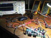
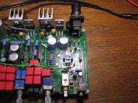
The photos below shows the setup:
In the first photo the scope ground lead is connected to that "relay circuit ground" point at the anode of D2. The ODA wall transformer isolates the board from the wall plug so you won't have any trouble with ground loops via a scope or meter ground when testing. In this case the scope is attached to the left set of switch contacts, which the relay coil loops through to cut power quickly during power-off. Measuring between these two points will put your meter right across the relay coil, showing if power is being applied to the relay.
I'm probably going to do another run of ODA boards in the near future and I will add a pad connected to the "relay circuit ground" point to make testing easy. There already is a pad for the output of IC11, the relay circuit voltage regulator.
Here are a couple of more ODA tips. 🙂
The ODA is completely silent turning on and off thanks to the relay circuit. Zero turn-on or turn-off thumps. HOWEVER, when doing fast power on-off cycles (during build testing) the amp needs to be "off" at least 3 seconds before turning it back on again or you could get a nasty thump. The reason is an RC delay circuit in the turn-on direction. On power down it takes at least 3 seconds for that capacitor to discharge.
And when making voltage measurements on the relay circuit please remember that it isn't referenced to ground, and in this particular amp it isn't referenced to the (audio) negative power supply rail either. The reference point is the negative lead of the big electrolytic C8, which is the same point as the exposed (top, anode) lead of the tombstone-mounted rectifier D2. That lead makes an easy place to connect. You could also just temporarily solder a small wire to that point to bring the "relay circuit ground" off the board for easy connection.
Things wound up with way because I'm taking the feed for the relay circuit voltage regulator off the first section of the ODA's power supply CRC filter section, between D2 and the first set of negative rail CRC resistors R19 and R20. Doing things this way provides a huge amount of isolation between the relay circuit (and power line!) and the audio power supply parts.
The photos below shows the setup:
In the first photo the scope ground lead is connected to that "relay circuit ground" point at the anode of D2. The ODA wall transformer isolates the board from the wall plug so you won't have any trouble with ground loops via a scope or meter ground when testing. In this case the scope is attached to the left set of switch contacts, which the relay coil loops through to cut power quickly during power-off. Measuring between these two points will put your meter right across the relay coil, showing if power is being applied to the relay.
I'm probably going to do another run of ODA boards in the near future and I will add a pad connected to the "relay circuit ground" point to make testing easy. There already is a pad for the output of IC11, the relay circuit voltage regulator.
Attachments
Last edited:
Input switch positions and input jack shorting options for noise floor testing
Here is a brief review of how the input jacks, PCB holes for signal inputs, and input select switch on the ODA work, along with the ability to short them to ground for noise testing.
The ODA allows flexibility to wire the inputs up in all sorts of different ways. A 3.5mm input jack (J2) is on the front panel and RCA input jack (J1) on the rear panel. The front panel input select switch (S2) switches between the two. In addition there are PCB holes by each input jack to wire in inputs (JP1 for the rear RCA and JP2/JP3 for the 3.5mm). There are also a set of holes on the output of the input select switch (JP7) which are useful for sending the input signal to the pre-amp section.
The NwAvGuy O2 headamp has the 3.5mm input jack set up to short the inputs to ground when nothing is plugged in, via traces under the jack. If an ODAC is wired in those O2 shorting traces have to be cut, otherwise the ODAC output is shorted to ground. With the ODA I made the self-shorting 3.5mm input jack optional by using zero-ohm resistors under the jack (bottom of the PC board, R1 and R2) that can simply be left off if an ODAC is to be wired into JP2/JP3.
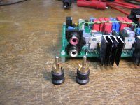
The rear RCA input jack (J1) does not automatically short to ground, as is common with RCA jacks. Instead shorting plugs can be used to short these when not in use, if you wish.
So here is an example, in the photos below, on some configurations for noise floor testing (or if you simply want to crank up your ODA with the inputs grounded to hear how silent the background is!). This particular ODA has the 3.5mm jack shorting resistors R1 & R2 installed (shorts the 3.5mm jack inputs to ground when nothing is plugged in).
* In the first photo 5054 the input select switch S2 is out, which selects the front panel 3.5mm jack as the ODA input. But in this case, since the R1 & R2 ground-shorting resistors are in place under the board as shown in the second photo 5057, the input to the ODA will be shorted to ground. This should result in a perfectly silent output on both channels, even with the volume pot and gain switch all the way up, which it does.
Note that in this photo RCA shorting caps are plugged into the rear RCA jacks, but they don't matter here at all since the input select switch it out, selecting the front 3.5mm jack - and JP2/JP3 PCB holes next to the front 3.5mm input jack if anything was soldered in there. But please realize that with R1 and R2 in place, if an ODAC was attached to JP2 and JP3, its output would be shorted (doesn't harm the ODAC if this happens) and wouldn't be heard. To use an ODAC those R1 & R2 resistors have to be removed, but that would also mean the inputs wouldn't auto-short anymore with nothing plugged in for noise testing. An ODAC wired into JP2/JP3 does not count as a short to ground for noise floor testing. Well that brings up the next photo...
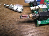
* The next two photos, 5061 & 5062, show a home-made 3.5mm shorting plug to use if you don't have R1 & R2 installed, because you are running an ODAC output into JP2 and JP3 next to the 3.5mm jack. Those are two 25 ohm 1W 1% metal film resistors soldered inside the 3.5mm plug because that is how NwAvGuy tested noise floor. He apparently left his dScope attached to the O2 input and the dScope has a 25 ohm output impedance. But in this case you could simply short the contacts inside the shorting plug, no real need to use resistors inside. Note that plugging the shorting jack into the ODA 3.5mm jack with an ODAC wired into JP2/JP3 will short the output of the ODAC, so unplug its USB input while you are doing noise floor testing.
* The next photo 5055 shows the input select switch now in, which selects the rear RCA jacks. In this case I have shorting plugs on both of those RCA jacks, which results in grounded ODA inputs. Same situation as with the 3.5mm jack selected above with either the R1 & R2 shorting resistors in place or the 3.5mm shorting plug used. The next two photos 5058 & 5059 are just a closeup of the RCA shorting plugs.
And very important: if you select the rear RCA jack (input select switch in) without RCA shorting plugs in the rear RCA jacks, you WILL hear random noise since the RCA inputs are now floating (unconnected). That is completely normal, of course. In fact you are more likely to hear random noise with the rear RCA selected and not grounded than with the front 3.5mm jack selected and un-grounded due to the long PC traces on the left side of the board to connect with the rear RCA jack. In normal operation with a source (and its output impedance) attached to the rear RCA jacks (if they are being used) this isn't an issue.
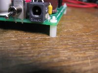
Lol - the list of stuff I include with ODA PC boards keeps growing. 🙂 Going forward I'm going to include a set of RCA shorting plugs and the 2mm nylon spacers shown in the next photo, used in the PCB corners for tabletop use if not using the metal case.
In the photos below you can click on the arrows in the lower left corner to zoom in, or hover over the photo to bring up the photo number.
Here is a brief review of how the input jacks, PCB holes for signal inputs, and input select switch on the ODA work, along with the ability to short them to ground for noise testing.
The ODA allows flexibility to wire the inputs up in all sorts of different ways. A 3.5mm input jack (J2) is on the front panel and RCA input jack (J1) on the rear panel. The front panel input select switch (S2) switches between the two. In addition there are PCB holes by each input jack to wire in inputs (JP1 for the rear RCA and JP2/JP3 for the 3.5mm). There are also a set of holes on the output of the input select switch (JP7) which are useful for sending the input signal to the pre-amp section.
The NwAvGuy O2 headamp has the 3.5mm input jack set up to short the inputs to ground when nothing is plugged in, via traces under the jack. If an ODAC is wired in those O2 shorting traces have to be cut, otherwise the ODAC output is shorted to ground. With the ODA I made the self-shorting 3.5mm input jack optional by using zero-ohm resistors under the jack (bottom of the PC board, R1 and R2) that can simply be left off if an ODAC is to be wired into JP2/JP3.
The rear RCA input jack (J1) does not automatically short to ground, as is common with RCA jacks. Instead shorting plugs can be used to short these when not in use, if you wish.
So here is an example, in the photos below, on some configurations for noise floor testing (or if you simply want to crank up your ODA with the inputs grounded to hear how silent the background is!). This particular ODA has the 3.5mm jack shorting resistors R1 & R2 installed (shorts the 3.5mm jack inputs to ground when nothing is plugged in).
* In the first photo 5054 the input select switch S2 is out, which selects the front panel 3.5mm jack as the ODA input. But in this case, since the R1 & R2 ground-shorting resistors are in place under the board as shown in the second photo 5057, the input to the ODA will be shorted to ground. This should result in a perfectly silent output on both channels, even with the volume pot and gain switch all the way up, which it does.
Note that in this photo RCA shorting caps are plugged into the rear RCA jacks, but they don't matter here at all since the input select switch it out, selecting the front 3.5mm jack - and JP2/JP3 PCB holes next to the front 3.5mm input jack if anything was soldered in there. But please realize that with R1 and R2 in place, if an ODAC was attached to JP2 and JP3, its output would be shorted (doesn't harm the ODAC if this happens) and wouldn't be heard. To use an ODAC those R1 & R2 resistors have to be removed, but that would also mean the inputs wouldn't auto-short anymore with nothing plugged in for noise testing. An ODAC wired into JP2/JP3 does not count as a short to ground for noise floor testing. Well that brings up the next photo...
* The next two photos, 5061 & 5062, show a home-made 3.5mm shorting plug to use if you don't have R1 & R2 installed, because you are running an ODAC output into JP2 and JP3 next to the 3.5mm jack. Those are two 25 ohm 1W 1% metal film resistors soldered inside the 3.5mm plug because that is how NwAvGuy tested noise floor. He apparently left his dScope attached to the O2 input and the dScope has a 25 ohm output impedance. But in this case you could simply short the contacts inside the shorting plug, no real need to use resistors inside. Note that plugging the shorting jack into the ODA 3.5mm jack with an ODAC wired into JP2/JP3 will short the output of the ODAC, so unplug its USB input while you are doing noise floor testing.
* The next photo 5055 shows the input select switch now in, which selects the rear RCA jacks. In this case I have shorting plugs on both of those RCA jacks, which results in grounded ODA inputs. Same situation as with the 3.5mm jack selected above with either the R1 & R2 shorting resistors in place or the 3.5mm shorting plug used. The next two photos 5058 & 5059 are just a closeup of the RCA shorting plugs.
And very important: if you select the rear RCA jack (input select switch in) without RCA shorting plugs in the rear RCA jacks, you WILL hear random noise since the RCA inputs are now floating (unconnected). That is completely normal, of course. In fact you are more likely to hear random noise with the rear RCA selected and not grounded than with the front 3.5mm jack selected and un-grounded due to the long PC traces on the left side of the board to connect with the rear RCA jack. In normal operation with a source (and its output impedance) attached to the rear RCA jacks (if they are being used) this isn't an issue.
Lol - the list of stuff I include with ODA PC boards keeps growing. 🙂 Going forward I'm going to include a set of RCA shorting plugs and the 2mm nylon spacers shown in the next photo, used in the PCB corners for tabletop use if not using the metal case.
In the photos below you can click on the arrows in the lower left corner to zoom in, or hover over the photo to bring up the photo number.
Attachments

Last edited:
Its "2" Years Old!!
I began my ODA journey almost two years ago!
Its been in use almost every day now....and its still a stellar headphone amp.
Recently I have upgraded to mostly 250 and 600 ohm headphones, Beyer T90 and recently the newer 2nd generation of the T1.
I didnt build the higher impedance 300+ version with the higher rails, and the volume level with the 600 ohm cans with 2x gain will indeed blow your head off!!
I have gone thru several other solid state amp builds and a Bottlehead Crack and a Schitt Vahalla 2 both OTL designs.
Why, because I wanted to see and hear for myself how well these amps would work with 600 ohm headpones...I never spent much time with the ODA and the T1's , just got them a month back...
I have been test listening to these cans with the tube amps, why, again these amps are hightly touted as being a very good match for high impedance cans. So just last night I finally tried out the T1's with the ODA.
I was totally shocked at how good the ODA works with the T1's, absolutely stunning...
The ODA has more than enough power to play the headphones extremely loud.
Compared to the Schitt V2 and Bottlehead Crack, the ODA is just absolutely "clear" and the overall presentation is wide and wonderful.
I am an objective guy, but last night the music transcended the equipment, it was like being there...almost (lol)..
I have done many blind tests with help from friends, and look forward to others opinion on this combination...but I will tell you that the ODA is something special with these T1's.
I honestly do not think with these cans and ODA it can get any better.
I am still building (2) more amps, why, because I like to!! Ha! But I seriously doubt that they will really be any better sonically to my ears....
So Happy Birthday "ODA" and thanks to AGDR for dreaming this one up, yes I know that NwAvguy is the originator for the basic design, but AGDR has taken the time to exploit it and make it better all around..
My hats off to you!!
Alex
:>)
Note: IMO I rate as: ODA: 9+ out of 10, Schitt Vahalla 2: 8+ out of 10, Bottlehead Crack: 7.5 out of 10
Last edited:
So Happy Birthday "ODA" and thanks to AGDR for dreaming this one up, yes I know that NwAvguy is the originator for the basic design, but AGDR has taken the time to exploit it and make it better all around..
My hats off to you!!
Alex
:>)
Thank you, Alex! 😀 I appreciate the review.
The bulk of the credit goes to NwAvGuy. My version of an ODA is essentially his O2 design "on steriods". Same fixed regulators, just better ones. Same gain stage, just a better chip (all the better chips are SMD like this and he wanted to keep the O2 all through hole). Same pot in the middle, just lower value for lower Johnson noise, taking advantage of the gain chip's high drive capability. Same output chips, just more of them. And all the stuff that wouldn't fit in the O2 case - rear RCA, front 1/4", headphone relay circuit, place for a Zobel (never used and never needed so far!), optional pre-amp, 4 position gain switch, clipping indicator, etc.
Interesting to me that your T1's beat out the T90's by such a wide margin! I've read many good reviews of those. Yeah these days the headphones all have such high sensitivity numbers that 600R is no longer hard to drive at all. With the older headphones it took the combo of 600 and low sensitivity to require high drive voltage swings.
Thanks for all your efforts in doing the fully-blind A/B reviewing. I know that is a huge amount of work! 🙂
Small update on my ODA build.
I have decided to make my own case for ODA, that calls for a DIY heatstink too.
With this this heatsink I could not have mounted the hatsink via clips beacuse of the caps and diodes on board so I had to drill the heatsink and thread it.
Rear panel CAD plans Help a lot with this.
It is pretty hard to get those hole right just by hand even with printed plans glued on the heatsink you have to be very precise and hammer in dots before drilling and threading-this step is crucial!
Here are some photos.
I have also opted for out impedance selector. It can be very useful with some headphones, IEM's or older headphones because it changes the frequency response in bass region.
I must say, after spending some time with this amp - I am so amazed. There is a very musical quality to it while it remains quiet, clear and resolving mostly with the HD650.
With all the build options and features this amp has. This is a pure DIY joy and sounds amazing!
More updates are coming soon with the DIY steel sheet case and the fancy wooden case over it.
Again, thank you agdr for all the help. Great job with ODA!
Last edited:
Hey Bozac....glad your enjoying the ODA, it is indeed special amp to me....I have built a bunch of DIY amps and several commercial amps in the past few years and my favorite is the ODA.....
Its now a "rare" beast....so enjoy and take good care of it!!
Alex
Its now a "rare" beast....so enjoy and take good care of it!!
Alex
Small update on my ODA build.
I've been wondering how your build was going! I nearly sent a PM over the weekend. 🙂 Thanks for the update!
OK, you win the award for best heat sink! That is fantastic. 😀 What a great fit. You even drilled and tapped holes for the bolts. Very nice work.
Just a reminder to anyone else reading this, like Bozoc says he isn't mounting his ODA in the standard Box Enclosures case where the voltage regulators would heat sink to the rear panel. Bozoc is mounting the board in a larger box, so additional heat sinking is needed on those chips if used on an ongoing basis. I ship the board with some small temporary heat sinks to use for testing, until a case rear panel arrives from Box Enclosures. To use the board at full power though, without the case rear panel, requires additional heat sinking like this.
I see that I can zoom way in on your posted pictures by rotating the wheel on the mouse! Your board looks terrific, and so does that damping factor rotary switch. You are the first person that I'm aware of who has implemented it. I agree, damping factor does make a difference. I've tried various small output series resistors with various headphones. Switching over to subjective listening vs. purely objective measurements, changing the damping factor a little can help with the listening enjoyment of some headphones and IEMs.
Hey you should post some pictures of the bottom of your board too! Your soldering is really some of the best I've seen.
I'm glad you are liking the amp! 😀 Please do post those case pictures.
Last edited:
Hi Alex! I'm glad the ODA is still holding its own. 😀 I know you have quite a collection of headamps now!
- Home
- Amplifiers
- Headphone Systems
- A version of an O2 Desktop Amp (ODA)