Its now a "rare" beast....so enjoy and take good care of it!!
Alex
I will do my best adydula. 😉
OK, you win the award for best heat sink! That is fantastic. 😀 What a great fit. You even drilled and tapped holes for the bolts. Very nice work.
Heatsink is probably and overkill since it just gets war, but that is good thing.
I used the mounting kit and also checked that none of the IC's are electrically connected to heat sink body.
I see that I can zoom way in on your posted pictures by rotating the wheel on the mouse! Your board looks terrific, and so does that damping factor rotary switch. You are the first person that I'm aware of who has implemented it. I agree, damping factor does make a difference. I've tried various small output series resistors with various headphones. Switching over to subjective listening vs. purely objective measurements, changing the damping factor a little can help with the listening enjoyment of some headphones and IEMs.
If anybody is interested I used jumper wire, 32, 60, 80 and 120Ohms, 0.6W resistors for 5 output impedance options.
Hey you should post some pictures of the bottom of your board too! Your soldering is really some of the best I've seen.
I'm glad you are liking the amp! 😀 Please do post those case pictures.
Updated photos with back side of ODA .
First part of the case(metal one made from bent steel sheet)photos are commign soon, wooden case also after that. 🙂
I was thinking of making a bigger case and putting the transformer into the case separate from board compartment 5 centimeters below the ODA.
I was also thinking of bypassing rectifiers and adding this guys before linear regulators.
But I will just make a separate box with transformer in it. 😀
Hi bozoc,
Hey you know a true DIYer when the bottom of the board is as interesting as the top! 😀
I would recommend going with the transformer in the separate external box, if possible. Keeps the magnetic field and higher voltage lines completely out of the box, which was always one of the plusses in using a wall transformer. I can't tell if those Meanwell supplies are switching - they probably are - I definitely wouldn't recommend putting a switcher in the box, to keep any chance of switching noise out.
Great work! I'm looking forward to seeing how that case looks!
What's the state of this project?
Is this project in it's current state doable? Are all the parts availible? I'm thinking about building this (first project this hard, but I feel like pushing my limits), but I really don't want to go through all the reading if I find out I can't finish it. Also, if next revision is coming in less than a year, I would gladly wait...
Thanks
PS: Also wanted to ask you to do a kind of review (or tell me where to find one). I don't need numbers, I want to know how it sounds. Does it have the same signature as O2 (very clean, very sterile, no fun) or is it different?
Last edited:
Is this project in it's current state doable? Are all the parts availible?
I do still have PC boards available! I thought I had sold them all but discovered I was looking in the wrong place. 🙂 The board comes with quite a bit of stuff:
- Twelve 1 ohm, 1/8W, metal film resistors for the output balancing. Mouser and Digikey do not stock these.
- The red LED used for the clipping indicator. Now discontinued at Mouser
- Two 5.49K resistors, no longer stocked at Mouser
- Two 130 degree blue chip LED resistors, no longer stocked by Mouser.
- 22 AWG silver coated Teflon wire used for jumpers.
- Two temporary heat sinks to use on the two pre-regulator chips until you have a back panel.
- M3 button head (2mm allen) stainless steel bolts, lockwashers, and nuts for mounting the 4 voltage regulators and pre-regulators on the rear panel, and the heat-sink on IC11. Also includes two truss head screws for securing the two vertical RCA jacks to the panels.
- The six NJM4556A output chips as a tested and matched set
- The two LME49990 gain chips, now discontinued but I have them.
As for reviews, take a look at the last 3 or 4 pages of this thread. Adydula and most recently bozoc, just a few posts back, have posted their listening impressions. I don't review my own stuff - too much self over-hyping going on in some other audio web sites. 🙂
The ODA is about 1/3 surface mount soldering, although it is the larger 1206 size. The rest is through-hole.
I don't have plans to make changes in the forseeable future, although I probably will send out another board run when these boards are gone.
I see that I need to update my list of what comes with the board. 🙂 Adding those matched NJM4556A output chips is new as of bozoc's build, posts above, a couple of months ago. Those are SIP chips that solder into the board, so it is good to have them verified as working and matched upfront. If you should be interested best wait until next week and I'll have an updated list put together.
Last edited:
BOM v2.1 38
i am not sure what i need to buy and what not,
the green is for 300-600 ohms headphones so no need,
yellow, bass booster and zobel network are optional.
but what about the other yellow stuff, (Middle coupling, offset null zener filter
)
what part number i need exactly?
LED1 - LED3, if mouser is out of stock, what to do? alternatives? pm agdr?
IC1, IC2 GAIN STAGE is Discontinued by TI, i need them? alternatives?
"Headers are optional", which headers? all of them? (JP xx )
IC1, IC2 GAIN STAGE is Discontinued by TI, i need them? alternatives?
What are the part numbers for IC1 & IC2?
I can probably recommend alternatives if I know the part number of the originals. Are they LME49990?
This thread has been updated so many times, I lost track of it a while back.
(Op amp, single, ultra low-noise ultra low-distortion, SOIC-8What are the part numbers for IC1 & IC2?
I can probably recommend alternatives if I know the part number of the originals. Are they LME49990?
This thread has been updated so many times, I lost track of it a while back.
)-- Gain stage --
IC1, IC2 Texas Instruments LME49990MA/NOPB
thanks, i want to build it, but now i see that O2 more famous build to this day,
maybe i should build the o2 (if there a version without batteries) or you think oda would be "better" beacuse i didnt see even 1 compare between the two
The LME49990 is a single, bipolar op-amp that I've tried in numerous applications and found its SQ fair at best.
Some people around here seem to go nuts over it perhaps because of it's published specs. or because of its "vanishingly low residual distortion".
I see that the designer for "The Wire" headphone amp uses the same op-amp along with the "sterile sounding" LME49600 National buffer.
A comparable single, bipolar op-amp to the '49990 is the LT1468.
Having used both, I easily prefer the SQ of the '1468 over the National offering.
But...if I were you, I would just stick to building the O2.
IIRC, the O2 uses easy-to-find and great sounding JRC(NJM) dual op-amps.
The LME49990 is a single, bipolar op-amp that I've tried in numerous applications and found its SQ fair at best.
Some people around here seem to go nuts over it perhaps because of it's published specs. or because of its "vanishingly low residual distortion".
I see that the designer for "The Wire" headphone amp uses the same op-amp along with the "sterile sounding" LME49600 National buffer.
A comparable single, bipolar op-amp to the '49990 is the LT1468.
Having used both, I easily prefer the SQ of the '1468 over the National offering.
But...if I were you, I would just stick to building the O2.
IIRC, the O2 uses easy-to-find and great sounding JRC(NJM) dual op-amps.
why if you were me you'd be sticking to the O2?
if you saying that you prefer the '1468, are there any projects around that you could recommend? (didn't found here for some reason).
i don't have enough exp to design my own op-amp :<
i see i can build "the wire" amp easily as it require almost nothing compere to the o2.
about easy-to-find its no problem, i have a supplier that can supply any non discontinued chip.
Hey Guys,
I can attest to the awesome qualities to this ODA headphone amp. Mine has been in use daily for months and months..and its always worked very well with any headphone I have used from 32 ohm to 600 ohms....
I have compared to many other DIY SS amps and commercial amps and AVR's. Its as good if not better than most amps.
AGDR has done a great job in this one...if you can get a board dont pass this one up!
Its a winner and will become a rare amp.
Alex
:>)
Count me in adydula.
I can also attest to the qualities of ODA.
ODA gives you a lot of customization options.
Reading thread history and development with agdr being extremely helpful to me and answering my questions made me appreciate this amp even more.
First build I did was O2 with some mods... Not only did ODA beats O2 in technical performance and sound wise but also some commercial amps I heard sound inferior to ODA IMO.
If you decide to build it, you wont regret it.
Plus, as the adydula said it - it is a very rare amp 😉.
ODA updated materials posted! BOM, board package contents, Mouser scan
Hi Guys!
I'm sorry about being scarce on the forum lately, just a lot going on. 🙂 Bozoc and Alex - a big thanks for your comments and feedback on this project!
I've had a couple of board inquiries last week. I've finally done an update on the materials that I've been meaning to do for awhile. A revised BOM is posted out at the project Google drive link now, in the first post of this thread and here (and attached below)
ODA 7_9_2014 V2.1 fabricated - Google Drive
Then I've fed this BOM to the BOM-scanner at Mouser to get a current read of stock available. The stored BOM I had there for the ODA was a couple of years old. Taking Mouser's stock into account I've adjusted the "board package", as I'm calling it now, which is at this link on my website
ODA prices
That whole list of stuff comes with the bare PC board, which is why this update has been on the back burner for awhile. I'm not supplying just the bare boards without these parts since they are essential to getting it built properly. On that list are the now-discontinued LME49990 gain chips, which i have and come with the package. Also the six NJM4556AL chips now come with, as a tested matched-set. That change was made thanks to Bozoc's great work in assembling his ODA. Thanks again, Bozoc! The ODA build will work just fine with random NJM4556AL chips from Mouser, but pre-testing them and matching them (per channel) like this gets you the absolute lowest DC output offset result. So when you are figuring up the total parts costs at Mouser, be sure to subtract these various parts that come with the board kit.
Also just a reminder that two of the parts, the two Linear Technology LDO voltage regulators, are only available at Digikey since Mouser doesn't stock LT. But I also have them. And a reminder that the ODA uses an AC-to-AC wall transformer, something Mouser and Digikey no longer stock but Jameco.com does (part number at Jameco in the BOM). That transformer is for the USA wall voltage and socket. If you are outside the USA then you are going to have some extra work to do in boxing up a small torroidal transformer and putting a 5.5mm/2/1mm power barrel plug on the end of the secondary output wire.
Some really good news! In Mouser-scanning the ODA BOM I discovered they now stock (or will, new part on order) the 10% version of the 4.7uF WIMA film capacitors for just $0.85 each, vs. the $3.63 each of the 5% part which previously is all they stocked. The ODA uses 12 of those, if you use the 1K pot, so that alone drops the ODA parts cost by $33! And I see a 5% version (on order) that is tape-and-reel, vs the bulk, also selling for $1. I need to research that part version a bit more. Might be possible to still have 5% and save a bunch of money at the same time.
The bad news is all versions of the 4.7uF WIMA film are shown as "on order", but the good news is the 10% version shows a "shipping date" of 9/29, 3 days ago, although they still show as out of stock. So with any luck they should be in stock day now.
As for the rest of the BOM parts there were 3 or 4 that were out of stock and on order. I was able to come up with equivalent alternate parts. Out in the notes column those are shown as "alt:". Except for one part, the two 10R 25 turn trimmer pots which are on order there, but as luck would have it I did a big buy of those. I've included those two trimmers with the board package and will keep them there until Mouser gets stock again. Same with the 1/4" Neutrik jack. I just noticed I've left that off the list, I'll add it tonight.
I have 3 boards left and 2 of those are "reserved" right now, waiting to see if the folks who contacted me last week wind up getting them now that the materials are updated. I'm going to have a new run of ODA boards done. There won't be any functional changes on the new run, it will be the same board. It will probably be a month or so before those are back.
Have fun and happy DIYing! 😀
Attachments
Last edited:
Hi agdr,
is your offer still valid?
Whoops, sorry that I'm just now seeing this! Didn't intend to ignore. The post above is the current status of the ODA stuff. 🙂
i am not sure what i need to buy and what not,
the green is for 300-600 ohms headphones so no need,
yellow, bass booster and zobel network are optional.
but what about the other yellow stuff, (Middle coupling, offset null zener filter
)
what part number i need exactly?
LED1 - LED3, if mouser is out of stock, what to do? alternatives? pm agdr?
IC1, IC2 GAIN STAGE is Discontinued by TI, i need them? alternatives?
"Headers are optional", which headers? all of them? (JP xx )
Whoops - another post I'm just now seeing. 🙂 Post 993 above has the latest update, but in general..
The two LME49990s, IC1 and IC2, come with the board package. They are discontinued but I still have them for this project. Originals, not fakes, which is about all that is available on eBay these days (the fakes). If someone gets a poor-performing LME49990 it could very well be a fake if bought since they were discontinued.
LED 3, the red through hole, comes with the board package. LED 1 and LED 2, the chip LEDs, come with the next couple of board packages just because I have a few of the Everlight brand left. 🙂 But I have found an exact equivalent part from Lite-On and listed that for LED 1 and LED 2 in the latest BOM out on the project Google Drive link in the first post in this thread.
The headers apply to the PC board holes in lines 37 -40 in the current BOM. Those would be just the standard 0.1" pitch header. But in all the ODA's I've built I've yet to use a header. I just leave the PC holes open.
I recommend leaving off the Zobel parts and bass boost parts. I have a note about it now at the top of the BOM. I left a place for a Zobel when I designed the board in case of stability problems, but none ever showed up. I was thinking about AMB's b22 headamp at the time, which I know several folks have needed Zobels to stabilize. And bass boost I now feel is best done on the source end rather than in the headamp, as with any other effects. You get a lot more control over it that way.
For the yellow highlighted stuff I have notes in the notes column about each item. If any more information is needed by anyone do give me a PM 🙂
The ODA is a much bigger project than NwAvGuy's O2. The O2 is all through-hole with parts on one side of the board. The ODA is about half surface mount, although I've kept it to the larger 1206 size, and has parts on both sides of the board. The O2 has about $30 in parts at Mouser. The ODA has about $170, but a few things can be subtracted from that now that come with the board (used to be $200, but now that Mouser has cheaper WIMA film 4.7uF's it is $170). The O2 uses the small B2-080 case and only needs a drilled front panel. The ODA uses the bigger B4-080 case and requires drilled front AND rear panels. I would *highly* recommend building an O2 headamp first before trying to build the ODA.
Last edited:
Mouser status of the various WIMA 4.7uF 63Vdc/40Vac film capacitor versions
I was able to call Mouser today and get a clarification on the status of the three versions of the WIMA 4.7uF 63Vdc/40Vac film caps used in the ODA. The current BOM I have posted has all 3 versions listed, with 2 of them listed as alternates in green background. All show as out of stock with more on order, but they have various "estimated ship dates". 2 are "bulk" packaged (loose caps in a bag) while one is a tape of some sort. All have exactly the same size capacitor body. BOM numbers C25-C29, C30-C34, C40, C42 (12 needed all total if using the 1K potentiometer, 6 total with a 5K potentiometer).
MKS2C044701M00KSSD: This is the 10% version of the 4.7uF 5% capacitor that has been in the BOM for several years. The "win" here is being vastly cheaper at $0.85 each vs. $3.93 for the bulk 5% version. 12 are needed so that really adds up. Mouser shows no stock, yet an "estimated ship date" of 9/29/17, 5 days ago! I wasn't clear if that ship date was the manufacturer to Mouser, or Mouser to the customer. Turns out it is the latter. 9/29/17 really is the date Mouser expected to be able to ship these caps, but she says the manufacturer has a delay of some sort. The have no further information about the delay she says. So... cross your fingers that these show up any day now. These are "bulk" packaging like the previous 5%, ie loose capacitors in a bag.
MKS2C044701M00JSSD: The 5% version of the capacitor which has been in the BOM for several years, at $3.63 each in 10+ quantity, is showing an "estimated ship date" of 12/27/17. Expect a long wait there. These are "bulk" packaging, ie loose capacitors (not on a tape and reel).
MKS2C044701M00JO00: A 5% version of the capacitor which is on some sort of tape and reel. I can't figure the mechanical diagram on the datasheet for the tape out on this one, so unfortunately I'm not going be be able to say if the leads on these will fit properly until they arrive and I can order one. The body size is correct, but the lead spacing and type is uncertain. They are $1.06 though, much cheaper than the bulk 5% version above. The savings is huge given 12 of these caps. $3.93 - $1.06 * 12 = $34! This version is showing an "estimated ship date" of 11/15/17, about 5 weeks from now. The big plus about this version is you get to retain the 5% tolerance at a much lower cost.
Last edited:
i just found out that there no gerber files for the v2.1 :<
That is right, I had to pull those a year or two ago when a commercial company was attempting to make a commercial product with them. All the materials and project itself are for DIY use. The PC boards that are part of the board kit are priced at nearly cost anyway. I think the actual board cost, with shipping from china, was $9.50 in the (small) quantity I had fabbed. In the board kit I believe I have them at $10.50 or $11. Makes up for the time I spend extracting boards from boxes and bagging them up. If I was attempting to make a profit on them I would have them priced at $20 or such.
Last edited:
4.7uf capacitors not available - board kits on hold for now.
Well Mouser and I have been exchanging nasty-grams this afternoon. The version of the WIMA 4.7uF film (the 10% bulk pack) that showed "expected ship date 9/29/17" now shows no ship date and none on order. Pfffttt. Mouser is telling me that was a large order that was pre-placed by someone, but that explanation doesn't quite add up. Every other part I've seen for years now with and "estimated ship date" and a quantity specified arrived on that date and in stock in the quantity indicated.
At this point I really can't trust the "estimated ship dates" of the other two versions of the capacitor. I give up on Mouser and I've placed a special order with someone else for a bunch of these. Should be here mid-November with any luck. Given the lack of these capacitors, and given that an ODA can't be built without them, I'm not going to have any more board kits available until these things come in. I put a lot of emphasis on people actually being able to build these projects and not getting stalled out for lack of parts. i'll post when the caps come in.
In the meantime I've posted another updated BOM out on the project Google Drive link. The one change is that I've located an exact replacement part for the red LED, which is now the one listed. No need to ship one with the kit anymore.
Last edited:
NJM4556AL matching and 4.7uF WIMAs on order at Mouser
An update on a couple of things for folks bulding this amp project. 🙂
Looks like I won a round at Mouser. They have ordered 3000 of the 10% 4.7uF WIMA film caps. The bad news is with the 22 week lead time they are not expected until next March. I've ordered some through another source that should arrive mid-November, if anyone needs the caps.
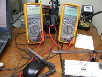
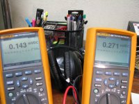
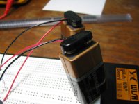
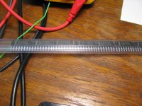
I did the matching on a bunch of the NJM4556A chips last weekend and took some photos to show how it is done, below. 🙂 Not hard, just a bit time consuming. Close counts here. Not looking for exact matches, as with jfet matching, since the zeroing circuit will cover quite a range. Just looking for any that are particularly different from the rest, to throw away.
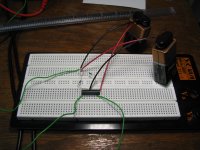
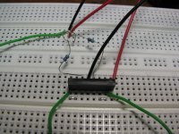
* The first 5 photos show the test setup. We are looking at output DC offset voltage here. Just a solderless breadboard with +/-8.7Vdc applied to the chip from two 9V batteries (measured, to make sure the batteries are roughly equal). The non-inverting inputs of the NJM4556A sections are returned to ground through a 4.99K resistor. This is important! If you just ground the inputs (without using the series 4.99K resistor) all you see is the inherent input offset voltage of the op-amp, which will be roughly centered around zero (both polarities). But if you use the actual 4.99K ground return resistor from the circuit, the input bias current of the NJM4556AL times the resistor value produces about half of the resultant DC output offset voltage. And it also skews the polarity of the output almost always positive, due to the consistant direction of the input bias current at idle (and AC zero crossings).
The net result: your measured DC output offset voltage will be nearly all positive with respect to ground. That is what the ODA's DC zeroing circuit is designed to expect.
The output is tied to the inverting input on each section, as in the actual circuit, to form a voltage follower.
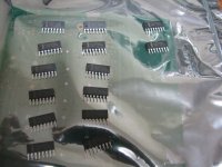
* The next photo shows a tube of the NJM4556ALs from Mouser
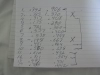
* The next 2 photos show the results. I've numbered each chip tested out of the tube and placed them on an anti-stat bag. From the hand-written results you can see that I've marked out chip #2 because that second section was all the way up at 1.37mVdc, way out of the average of the others just looking at the list here. That one went in the trash, as did #8 since the first half measured slightly negative polarity. I didn't have it marked at this stage, but #4 also eventually went into the trash. Once I did a second tube of chips I decided that 0.175mVdc on the first section was a bit lower than average too. All the rest of the measurements are just fine. You can see how I matched them up from the lines at the right. I put #1 and #5 together so the higher 0.906mVdc from the second section is reduced by the lower 0.360mVdc on #5's second half. Same with the first halves, matching up the higher 0.721mVdc of #5 wit the lower 0.342mVdc of the first half of #1. Then #6 is relatively equal on both halves.
Again the DC zeroing circuit has a wide range, so close counts here. Does *not* have to be exact matching. Just getting rid of things like that 1.37V and the -0.148 help keep the zeroing trimpot in the middle and not out slower to one end or the other.
Also just a comment, as can be seen a certain number of the chips go in the trash here. 3 in this case. On the next tube of chips I that did 4 got thrown away. So that also figures into why the cost of the NJM4556AL matched set in the ODA board kit is about 2x the $0.73 cost of the chip at Mouser, along with the time it takes to do this matching.
An update on a couple of things for folks bulding this amp project. 🙂
Looks like I won a round at Mouser. They have ordered 3000 of the 10% 4.7uF WIMA film caps. The bad news is with the 22 week lead time they are not expected until next March. I've ordered some through another source that should arrive mid-November, if anyone needs the caps.
I did the matching on a bunch of the NJM4556A chips last weekend and took some photos to show how it is done, below. 🙂 Not hard, just a bit time consuming. Close counts here. Not looking for exact matches, as with jfet matching, since the zeroing circuit will cover quite a range. Just looking for any that are particularly different from the rest, to throw away.
* The first 5 photos show the test setup. We are looking at output DC offset voltage here. Just a solderless breadboard with +/-8.7Vdc applied to the chip from two 9V batteries (measured, to make sure the batteries are roughly equal). The non-inverting inputs of the NJM4556A sections are returned to ground through a 4.99K resistor. This is important! If you just ground the inputs (without using the series 4.99K resistor) all you see is the inherent input offset voltage of the op-amp, which will be roughly centered around zero (both polarities). But if you use the actual 4.99K ground return resistor from the circuit, the input bias current of the NJM4556AL times the resistor value produces about half of the resultant DC output offset voltage. And it also skews the polarity of the output almost always positive, due to the consistant direction of the input bias current at idle (and AC zero crossings).
The net result: your measured DC output offset voltage will be nearly all positive with respect to ground. That is what the ODA's DC zeroing circuit is designed to expect.
The output is tied to the inverting input on each section, as in the actual circuit, to form a voltage follower.
* The next photo shows a tube of the NJM4556ALs from Mouser
* The next 2 photos show the results. I've numbered each chip tested out of the tube and placed them on an anti-stat bag. From the hand-written results you can see that I've marked out chip #2 because that second section was all the way up at 1.37mVdc, way out of the average of the others just looking at the list here. That one went in the trash, as did #8 since the first half measured slightly negative polarity. I didn't have it marked at this stage, but #4 also eventually went into the trash. Once I did a second tube of chips I decided that 0.175mVdc on the first section was a bit lower than average too. All the rest of the measurements are just fine. You can see how I matched them up from the lines at the right. I put #1 and #5 together so the higher 0.906mVdc from the second section is reduced by the lower 0.360mVdc on #5's second half. Same with the first halves, matching up the higher 0.721mVdc of #5 wit the lower 0.342mVdc of the first half of #1. Then #6 is relatively equal on both halves.
Again the DC zeroing circuit has a wide range, so close counts here. Does *not* have to be exact matching. Just getting rid of things like that 1.37V and the -0.148 help keep the zeroing trimpot in the middle and not out slower to one end or the other.
Also just a comment, as can be seen a certain number of the chips go in the trash here. 3 in this case. On the next tube of chips I that did 4 got thrown away. So that also figures into why the cost of the NJM4556AL matched set in the ODA board kit is about 2x the $0.73 cost of the chip at Mouser, along with the time it takes to do this matching.
Attachments
Last edited:
- Home
- Amplifiers
- Headphone Systems
- A version of an O2 Desktop Amp (ODA)