I just realized that I missed a couple of posts! Sorry about the delayed replies.
The mysteries of Windows! Good find.
If you have never soldered circuitry at all before the ODA would probably be too much. Best to start with something all through-hole like the O2 headamp. If you have done some through hole soldering before (but no surface mount( you could probably do OK with the ODA. I've kept the size of 99% of the surface mount parts to the larger "1206" size. The two things I considered essential though for surface mount work (as in, don't even try it without them!) are some right angle tweezers, a good circuit board vise like the Panavise 350, and a soldering station rated at least to 80W, fine (small width) desoldering braid, and some sort of solder sucker for cleaning out holes accidently filled, even if just a suction bulb or "solderpult" type. I have a part number for the tweezers in the build instructions, a common type on eBay for $3.
Done! 🙂 I already have changes posted for all the ODA builds out at the Google Drive links, including V2.1.
Both are true, although for two headphones the total current draw shouldn't be more than a HE6. So you could have two "normal" headphones (in terms of power requirements) or one HE6 / HE500 / K1000. I encourage using the ODA for two headphones. That is another great way to make use of the ODA's extra output current.
The 3.5mm and 1/4" headphone output jacks on the PC board are in parallel with no switch. You just get the same output at both. However, it would be really easy to cut the traces going from the 3.5mm output jack to the 1/4" jack and solder in an external panel mounted switch. Or even better, I included holes for connecting wires to run the output to somewhere else - that is JP22. Those holes come right off the output of the headphone relay. So with a little more trace cutting you could run JP22 to your external DPDT switch, then back from that switch to the 3.5mm jack traces and the 1/4" jack traces. Then you would have a switch that really did switch between the 3.5mm out and the 1/4" out.
I have set the playback mode in Control panel -> Audio hardware -> Odac properties -> Advanced from 16bit 44khz to 24bit 96khz and that SOMEHOW solved the hissing. I don't understand why. It just does though.
The mysteries of Windows! Good find.
How difficult do you think the ODA is to assemble? I have no experience with this stuff at all. I have a friend that knows how to solder, that's basically it. I mean, I don't want to bork everything trying to build it and have to try again. It's nice to learn stuff, building something like this, but only with somebody who knows what the hell we're doing. 😀
If you have never soldered circuitry at all before the ODA would probably be too much. Best to start with something all through-hole like the O2 headamp. If you have done some through hole soldering before (but no surface mount( you could probably do OK with the ODA. I've kept the size of 99% of the surface mount parts to the larger "1206" size. The two things I considered essential though for surface mount work (as in, don't even try it without them!) are some right angle tweezers, a good circuit board vise like the Panavise 350, and a soldering station rated at least to 80W, fine (small width) desoldering braid, and some sort of solder sucker for cleaning out holes accidently filled, even if just a suction bulb or "solderpult" type. I have a part number for the tweezers in the build instructions, a common type on eBay for $3.
You know what would be nice? If you made a changelog. So, you add the version number, date the change was added, and exactly what change each revision adds. Personally I love reading changelogs for some reason.
Done! 🙂 I already have changes posted for all the ODA builds out at the Google Drive links, including V2.1.
And so, I heard the ODA is capable of powering the HE-6, and also allows for two headphones to be plugged in? (Going off of what I was told in some other forum - My brain is pretty hazy right now.) So does it power both at the same time or is there a way to switch between them?
Both are true, although for two headphones the total current draw shouldn't be more than a HE6. So you could have two "normal" headphones (in terms of power requirements) or one HE6 / HE500 / K1000. I encourage using the ODA for two headphones. That is another great way to make use of the ODA's extra output current.
The 3.5mm and 1/4" headphone output jacks on the PC board are in parallel with no switch. You just get the same output at both. However, it would be really easy to cut the traces going from the 3.5mm output jack to the 1/4" jack and solder in an external panel mounted switch. Or even better, I included holes for connecting wires to run the output to somewhere else - that is JP22. Those holes come right off the output of the headphone relay. So with a little more trace cutting you could run JP22 to your external DPDT switch, then back from that switch to the 3.5mm jack traces and the 1/4" jack traces. Then you would have a switch that really did switch between the 3.5mm out and the 1/4" out.
Last edited:
FPE 20% off sale, Allied xformer overstock, update
I've run into a couple of helpful "sale" items for anyone thinking of building an ODA.
Front Panel Express is having one of their 20% off sales for orders up to $250 through August 10. Discount code is 2LGOC70F. That first zero is the letter O while the second is the number 0 and everything is in caps. Lol - now I really do have to get my rear in gear and get those vent holes added to the rear panel! Sorry about the delay, just haven't had time. Don't forget about the panel designs dace and kamilgd posted a few posts back in the thread. Both are terrific and both have vent holes. V2.1 of the ODA doesn't change anything with the panels, other than I would like to get vent holes added in the rear panel in some fashion.
The other interesting thing is that Allied Electronics has the power transformer for the ODA - the WAU16-2400 - listed as "excess inventory" and discounted to $11.62 from $21 normally. Mouser sells them for $20.71 and only have 4 left, so this also solves a potential out-of-stock problem. Allied shows 80 in stock. Just do a search on their site for WAU16-2400. Allied is one of the places that sells the B4-080 (and B4-160) cases. You could pick a power transformer for (relative) cheap on the same order as the case. 🙂 Allied has a few of the other ODA parts and a couple of those were also marked as excess inventory for 1/10 the price. I'll be posting a first pass at the ODA V2.1 BOM later tonight, and I have the Allied numbers added for the few ODA things they have.
An update on the V2.1 board building and testing. I have the full power supply built up now on a V2.1 board and it works. I'm going to use that board as the rear board in a 2-board ODA V2.1 build. The transorb across the power line is back - I realized that a leaded version can simply be soldered across the AC power jack on the bottom of the board. I have about 90% of the rest of a V2.1 board built and should be able to test it when some parts arrive from Mouser on Tuesday. If all works then I will finally be able to ship some boards out. 🙂 I'll send PMs to everyone on the waiting list when the time comes.
Last edited:
The ODA V2.1 PCB works
It works! 😀
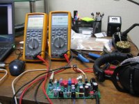
I finished an ODA V2.1 today and did some testing. Works great. No layout errors.
I want to run it 24hrs for a couple of days. I'll send PMs out to everyone on the PCB waiting list when the time comes, probably later this week. I have some LT3015 and LT1963A regulators on order (Mouser doesn't stock them but Digikey does).
It works! 😀
I finished an ODA V2.1 today and did some testing. Works great. No layout errors.
I want to run it 24hrs for a couple of days. I'll send PMs out to everyone on the PCB waiting list when the time comes, probably later this week. I have some LT3015 and LT1963A regulators on order (Mouser doesn't stock them but Digikey does).
Attachments
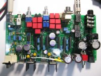
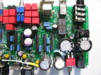
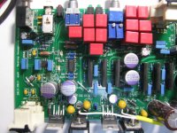
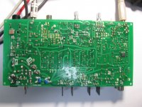

The new V2.1 boards arrived today already! Photos below. Now I'll build one up and test it. 🙂
Well a big "thank you" goes out to mgalusha at AudioCircle.com for his dScope tests on the ODA headamp - and to adydula for making the introduction! Mike has created a precision load box to use with the dScope testing with 1K, 5W, 10 turn pots to very closely match the loads on the two channels. I really appreciate his efforts. Setting up and running tests like this takes a huge amount of time and effort.
His dScope tests are ongoing, but I have at least one result to share so far that makes me pretty happy. In NwAvGuy's blog of his O2 headphone amp dScope test results here:
NwAvGuy: O2 Headphone Amp
search down for the heading "THD+N vs. OUTPUT & MAX POWER ON AC". In the graph there NwAvGuys shows the dScope THD+N percentages on the Y axis vs. RMS output voltages on the X axis, for several different output loads on the O2 headamp. The yellow curve shows that the O2's maximum output power, while on AC, for a 15R load (before severe distortion sets in due to clipping) is around 2.0Vrms at 0.0032% THD+N. That point is 266mW into the 15R load [(2Vrms^2 / 15R]. Going slightly above that output level for the O2 headamp the graph shows that the distortion shoots up to 1% at 2.2Vrms (366mW) with the onset of clipping.
So the maximum "clean" power NwAvGuy's O2 headphone amp can deliver to a 15R load is around 2.0Vrms, at 0.0032%THD. The ODA is capable of delivering many times more power into a 15R load, but the big question has been at what THD+N levels.
At a power level into the 15R load of 293mW, which is close to the O2's maximum "clean" 15R load power level from above, Mike's dScope measured a THD+N of 0.00207% for the ODA on one channel. The other channel measured 0.00203% with a power level of 283mW. Those THD+N numbers are about 36% less than the O2 headamp. The dScope is calculating the power output levels based on Mike entering 15R loads into the dScope setup screens. He measured those precision 1K, 5W, 10 turn pots for the output load to differ by only 0.05R from channel to channel.
The going up from there, which the O2 headamp can't do since it is maxed out at the 266mW, Mike cranked the ODA headamp up to an output power level of 1.17W into the 15R load. This is about 1.17W/0.266W = 4.4x more power than the O2 can deliver to a 15R load. Here his dScope measured a THD+N of 0.00201%, almost identical to the THD+N level at 283mW before, and still 36% less than the O2's THD+N level at its maximum "clean" output into 15R. The other channel tested very similar.
Going up further from there the ODA can crank out more power still, but his dScope showed the distortion rising a bit. He found the ODA's maximum "clean" output level into 15R, before a significant rise in THD+N (which indicates clipping, of course) was around 1.68W with a THD+N of 0.01232%. The other channel measured 1.6722W into 15R with THD+N at 0.00723%. The ODA will go slightly higher in output power, but the THD+N then shoots up dramatically (the start of clipping) as the dScope readings showed.
The difference in THD+N in the two channels is likely due to me sending Mike an ODA that has 0.5R balancing resistors on one channel and 2R resistors on the other channel. This seemed like a good opportunity to explore the effects of the parallel op amp balancing resistors on THD+N.
So that maximum ODA output level of 1.7W into 15R is 1.67W/0.266mW = 6.3 times the maximum power output of the O2 into 15R. The ODA power output level into 15R that would match the O2's 0.0032% THD+N at its maximum level would then be somewhere between the 1.17W and the 1.7W output levels, maybe somewhere around 1.4W or so, about 5X the O2's maximum 15R power level.
The results are what I was hoping for! One of the major design goals of the ODA was the ability to supply significantly more power into low impedance loads, for low-impedance low-sensitivity cans like the HE6 and HE500, than NwAvGuy's O2 headphone amp is capable of. And the hope was that it woild be able to do that at least as cleanly, in terms of THD+N, as the O2 and maybe just a bit more. It looks like that particular design goal has been met! 🙂
I am going to post all the "bad stuff" that crops up in the dScope testing as well as any "good stuff", like this particular measurement happened to be. No cherry picking on measurements. 🙂 That is where helpful design changes come from. Already the testing led me to discover that error of including the 15K gain setting resistors, as I posted about previously.
Again a huge "thank you" goes out to Mike for the dScope testing work! I will post a link to the dScope shots and/or video when the testing is all completed.
I also wanted to give a big thank you to John at JDS Labs for his offer to dScope test the ODA. I was going to take him up on that, but when the opportunity came up for someone in the DIY community (non commercial) to do the testing I went with that, in the spirit of NwAvGuy's original testing. Thanks John!
And finally the biggest "thanks" of all goes to NwAvGuy of course, for his work in creating the O2 headamp in the first place. I know that one of his posted concerrns in his blog was to "not mess up a good thing" in terms of the O2's measurements. Hopefully that ODA will meet that goal, at least in the majority of areas.
Nice work, agdr 🙂
Both are true, although for two headphones the total current draw shouldn't be more than a HE6. So you could have two "normal" headphones (in terms of power requirements) or one HE6 / HE500 / K1000. I encourage using the ODA for two headphones. That is another great way to make use of the ODA's extra output current.
At 7.25Vrms the HE-6 pulls 150mA of current. The ODA can manage 500mA, so couldn't the ODA (theoretically) drive 2 HE-6s? You'd only start getting into trouble when you try putting 7.25Vrms across 35R loads.
At 7.25Vrms the HE-6 pulls 150mA of current. The ODA can manage 500mA, so couldn't the ODA (theoretically) drive 2 HE-6s? You'd only start getting into trouble when you try putting 7.25Vrms across 35R loads.
You are actually right about that, I hadn't done the math! But there is an interesting trick that pops out of the math here. One single HE6 actually is close to the ODA maximum, if at 113dB output level (113dB is just where the spreadsheet breaks, see below) due to the voltage drive required being 6.67Vrms, close to the amp's 7.25Vrms max. But as more HE6 are added in parallel the impedance drops, increasing the current requirements from the amp, but actually dropping the amp output voltage requirement. And the ODA has no problem with current.
So the upshot is that while a single HE6 is close to the ODA max (in terms of output votlage), 2 or 3 paralleled HE6s are not near the max either in terms of voltage or current output. How about that for some odd math results. 🙂
On the ODA project's Google Drive link for the past V2.0 I have a "headphone types vs. ODA" folder with some spreadsheets for the various headphones at different dB levels, including the HE6 and HE500, here:
https://drive.google.com/folderview?id=0B67cJELZW-i8SXZrcktvTGl2Y28&usp=sharing
The spreadsheet is one that was posted on Head-Fi last year. It shows the amp votlage and current requirements for a givenn dB output level, given a headphones impedance and sensitivity numbers as inputs.
The HE6 is 50 ohms, so two plugged in at once would be 25R since the output jacks are wired in parallel. Plugging that into the spreadsheet in place of the 50 gives:
for 95 dB, two HE6 in parallel:
* amp output voltage: 0.59Vrms
* amp output current: 23.mA, then divide by 6 for 6 output op amps in pararllel in the ODA = 3.8mA. Each op amp is good for 60mA conservatively (actually 70mA by the datasheet and is what NwAvGuy uses)
for 113 dB (anything higher breaks the spreadsheet), two HE6 in parallel:
* amp output voltage: 4.7Vrms
* amp output current: 188.mA, then divide by 6 for 6 output op amps in pararllel in the ODA = 31.3mA. Each op amp is good for 60mA conservatively (actually 70mA by the datasheet and is what NwAvGuy uses)
So either dB level would be easy for the ODA. Just for fun I ran the math on 3 HE6 in parallel at 113dB:
* amp output voltage: 3.85Vrms
* amp output current: 230.mA, then divide by 6 for 6 output op amps in pararllel in the ODA = 38mA. Each op amp is good for 60mA conservatively (actually 70mA by the datasheet and is what NwAvGuy uses)
So even 3 in parallel would work! 😀 I've designed the ODA such that any volume pot setting into any load down to 16R is OK and won't overheat the output chips.
Good discovery on this issue! Thanks for the post.
Last edited:
Correction to my post above
Whoops. 🙂 I just realized in my last post the power shown in the spreadsheet for paralleled headphones would be that delivered by the ODA, but not that of each headphone anymore since there are now two (or more) headphones in parallel.
So the observations about being able to power 2 or 3 HE500 in parallel at the same time is still correct, but it won't provide any more maximum voltage swing than having just one HE500 attached. For 2 HE500 phones with the 6.67Vrms swing needed to get one HE500 to 113dB, the result is 267mA total from the amp or about 44mA of the 60mA available per output op amp.
Last edited:
Check this video out of the ODA driving a set of full range loudspeakers!!!
Quite amazing!!
https://www.youtube.com/watch?v=VTbWVEKzVpY
FYI
Alex
Quite amazing!!
https://www.youtube.com/watch?v=VTbWVEKzVpY
FYI
Alex
Check this video out of the ODA driving a set of full range loudspeakers!!!
Thanks again to mgalusha over on Audio Circle for the dScope testing! Very much appreciated.
He is being good enough to ship it back to me for some mods before the next round of testing. I want to remove the 15K resistors in the 1.1x gain position to make it 1.0x (and get rid of the associated Johnson noise). Also replace those test 2R balancing resistors on one channel with 0.5R to match the other, since the first round of dScope tests showed the 0.5R produce lower THD+N into the 15R. And finally completely remove the pre-amp feed so the tests are done on the base amp. As that one sits now it has a pair of wires coming off the input select switch holes and feeding the pre-amp chip, which puts that chip's input (and its additional input noise) in parallel with the signal input. Mike has also been using the rear RCA jacks so far which may have slightly higher noise due to the long connecting traces running up the left side. The next round of dScoping may have a test just through the front 3.5mm jack, where the single point chasis ground is also connected.
While boxing it up Mike made that video of the ODA driving a nice pair of desktop speakers! 😀 The ODA is designed so that any volume control position can be used with 15R loads and up with no worry of overheating the output chips (with the strandard +/-12.5Vdc power rails). I don't mention it in the materials but the ODA most certain can drive 8R and even 4R desktop speakers if the volume level is kept below certain amounts so that the output chips don't overheat.
Since there would be no way to know what that level on the volume control would be at 4R or 8R load without measuring the output voltage or doing the math I've left out mention for safety. But the ODA can drive an 8R load with a volume control level that results in up to 1.5Vrms output without overheating the output chips, using pure sine waves. 🙂 There is that issue of music power though, where with real music and not sine waves the average power dissipation is around 1/3 to 1/2 or so less than sine wave power, as in this case, allowing for even higher output voltages on the musical peaks.
Notice that the red clipping indicator LED/circuit is doing its thing on peaks, too. 🙂
Last edited:
I found this rather interesting post by NwAvGuy:
NwAvGuy: ODAC May Update
A good idea for ease-of-DIY, and you could use this to connect the ODAC out to either 3.5mm/RCA/ODA with a 3-position select switch (on back panel). It would also standardise the ODAC's position relative to the ODA, which could be beneficial for back panel layout.
NwAvGuy: ODAC May Update
The idea for the ODA is a 3 or 4 pin header will connect directly to the 4 pin terminal on the ODAC. There will be no wires. The header will help support the ODAC with the opposite edge hopefully supported in a chassis slot. If you solder wires to the 4 pin header now you would need to clear the holes out to use the header later with the ODA.
A good idea for ease-of-DIY, and you could use this to connect the ODAC out to either 3.5mm/RCA/ODA with a 3-position select switch (on back panel). It would also standardise the ODAC's position relative to the ODA, which could be beneficial for back panel layout.
A good idea for ease-of-DIY, and you could use this to connect the ODAC out to either 3.5mm/RCA/ODA with a 3-position select switch (on back panel). It would also standardise the ODAC's position relative to the ODA, which could be beneficial for back panel layout.
Good find! I handn't seen that quote in his blog. Interesting... sounds like he was fairly far along on his ODA design.
ODA V2.1 PCB's ready to ship.. PMs out tomorrow... BOM/stock update
I'm satisfied with the ODA V2.1 PC board build testing at this point, so out they go! 😀 I'll sent PMs out to the first half of the order interest list starting tomorrow, which will include the (all at-cost) payment instructions. The PMs are just to check if you are still interested - no commitment of any kind on getting the boards - and if so the payment details.
The order interest list and pricing list are here in the project's Google Drive:
https://drive.google.com/folderview?id=0B67cJELZW-i8Y2ttNE9tZ2NidTQ&usp=sharing
I've just posted an updated BOM and a full set of build photos at the Google Drive link in the first post in this thread. Here is the current story on stocking at Mouser. They have everything in stock except:
* Mouser is out of stock on the 1K 9mm (volume) pots, supposed to be back in stock next month. You can use the 5K 9mm pot instead, Mouser has both the audio taper and linear taper 5K's in stock. I have both shown in the BOM revision as alternate choices in yellow highlighting. The 5K pot is required if you are doing the the optional +/-15Vdc rail build for headphones 300R and up.
I do have a few of the 1K 9mm pots here. I'll make those available to buy at-cost on the price list and offer them up in order of the people on the waiting list, but just one pot per person to help out as many folks as possible.
* Mouser is out of stock on the dual RCA jacks used for the rear signal input and front pre-amp output. They are supposed to be in stock next month. Switchcraft makes a similar jack but the pinout is different. You can just leave these off your build entirely for now and solder them in later when Mouser gets stock again. The signal can still go in through the front 3.5mm jack just fine.
I do have a few of the dual RCA jacks here. I'll make those available to buy at-cost on the price list and offer them up in order of the people on the waiting list, but just one jack per person to help out as many folks as possible.
* Mouser is out of stock of the 40mcd 130degree LEDs used for the clipping window reference, back in stock next month. In the revised BOM I've listed an alternate part they do have in stock, the slightly brighter 100mcd 60 degree SMD LED. Note these LEDs have to be blue since they are used as voltage references. Vf of other colors is different.
* C5 changes from the 0.01uF 630V SMD cap to 0.01uF 100V SMD because the new transorb across the AC line takes care of incoming transients. That capacitor is the snubber frequency reduction capacitor. I had the voltage so high originally just to survive line transients since it is across the AC line, but the transorb takes care of that now. If you have the old 630V cap that is OK - Mouser is also out of stock of the 630V so the change is coming at a good time.
In addition to the 12 0.5R 1/8W balancing resistors and the 22 gauge hookup wire, I'm included two heat sinks and mounting bolts with each board. The heat sinks can be used on the pre-regulator chips (LM317/LM337) as in the build photos, to test the board until you get a rear panel for heatsinking.
There are plenty of PC boards available so if anyone wants a ODA board who isn't on the waiting list, just send me a PM.
I've had some requests for ODA PC boards where just the surface mount components are soldered on, with the through-hole left to DIY. I may start offering those up, but not at cost (this round is all at-cost on the PCBs and parts). If interested in those partially-stuffed PC boards keep an eye on my vendor thread here in a couple of weeks:
http://www.diyaudio.com/forums/vendors-bazaar/237226-parallel-njm4556al-two-stage-amp.html
Last edited:
Good find! I handn't seen that quote in his blog. Interesting... sounds like he was fairly far along on his ODA design.
This was in an ODAC update so I think he was just designing the ODAC with ease of use in mind. This connectivity option was probably just that - so he wouldn't have to revise the ODAC PCB if he wanted to add it later, which would have been complicated, what with it being sold pre-assembled.
This was in an ODAC update so I think he was just designing the ODAC with ease of use in mind. This connectivity option was probably just that - so he wouldn't have to revise the ODAC PCB if he wanted to add it later, which would have been complicated, what with it being sold pre-assembled.
That is a very interesting find! 🙂
More about Mouser out-of-stock parts
I forgot about something. If you use the 5K volume pot shown on the BOM (Mouser is out of stock of the 1K pots for a month) then you also have to use the 24.9K ground return resistors (R42, R42) shown instead of the 4.99K or it will load the pot. The 24.9K's are shown as an alternate in the BOM for use with the 5K pots. If you are doing a higher voltage +/-15Vdc power rail build for phones 300R and up, then the 5K pot and 24.9K resistor are the standard things to use, as shown in the BOM and explained in the build instructions.
I've decided to just buy a bunch of the 1K pots and dual vertical RCA jacks once Mouser gets those back in stock, then sell them at-cost for any of the builders that need them. That way I can send them in cheaper USPS first class mail and you'll avoid Mouser's larger shipping fee.
If you wind up using a 5K pot and want to switch to 1K later it will be hard to get out unless you have a vacuum solder sucker like a Hakko 808. I would suggest soldering small lengths of wire, like a couple of inches, to each of the pot leads and then run those down to the PC board holes (you would have to leave the front panel off the ODA for a month, of course). That way it would be fairly easy to unsolder each pot wire lead from the ODA pc board and clean the holes with de-soldering wick.
There should not be any audible difference between using a 5K volume pot and a 1K. The 1K (and 4.99K ground return resistor) just produce less Johnson/thernal noise, a small reduction that would show up in the dScope testing.
Last edited:
What tweaks do I need to go from 2.0 -> 2.1 or it might be easier to get a few 2.1 boards as a new start?
Regards
Regards
What tweaks do I need to go from 2.0 -> 2.1 or it might be easier to get a few 2.1 boards as a new start?
Regards
Hey good question, I'll bet several of the V2.0 builders are wondering. The good news is that nearly all the changes to the V2.1 board are cosmetic, to make building a little easier in a few spots, and there should be no audible difference at all. If you have a V2.0 board there is no need at all to build a V2.1 - unless you just want to! 😀
I have a full change list between V2.1 and V2.0 posted at the Google Drive link, but the cosmetic things include: making the 1/8W through-hole resistor pads 1mm longer so the resistor leads don't have to be bent so close to the body; made some part text on the board larger, some smaller, moved some around to make it all more readable; rotated JP19 90 degrees so it jumpers up an down like JP18; removed the second ground hole from JP8 and JP9 since a single wire works - don't have to use coax, etc. The only error that I corrected was those 1N4004 diode holes being on the small end of the lead thickness range, but hopefully you have received those diodes that do fit in the mail by now.
I've added a few things on V2.1 though that are probably all "engineering overkill", but they are low cost so why not. 😀 You can easily add this stuff to V2.0:
* I added a transorb across the AC jack to absorb any fast moving power line transients. It was "D17" on the V2.1 board, but I screwed up and put the wrong pad down. So now it is a 500 watt 23Vac (for the 16Vac transformer) transorb with leads that you can just solder right across the AC jack leads on the bottom of the board, under the jack, on either V2.0 or V2.1. I'll take some photos and post out on the V2.0 google drive folder.
* I added a fuse, a 2.5A slow blow pico fuse. Easy to add this one on V2.0 but cutting one trace near the AC jack and soldering it in under the PC board between the AC jack and the C7. I'll post a marked up photo of that too. The transformer is fused so this is a second line of defense. In fact, I can testify to the tranformer being fused, since when I screwed up and tested V2.1 with the unidirectional transorb (should have been bidirectional) it opened up the transformer secondary in about 2 seconds, lol. 😱
* C35 and C36 in the power supply section have gone from 10uF 35v to 22uF 35V. I ran into a data sheet for the LM regulators that suggested the higher value when the bypass capacitor on the adjust pin is being used. The good news is the new capacitor will fit just fine in the V2.0 boards! It wasn't supposed to, the size Mouser has listed is larger and I went to some work moving the layout around in V2.1 to accomodate it. Then the part gets here and it is smaller and fits just fine on the original layout. Argh, Mouser.
* I've now specified small leaded 0.01uF 100V MLCC COG ceramic capacitors that solder right across the leads of the 4 large power supply filter caps (the 1000uF and the 820uF), soldered on the bottom of the PC board. On V2.1 the two caps on the 820's are leaded while the two on the 1000's can be 0805 SMD or leaded. For V2.0 just use 4 leaded caps. The addition just helps with rejecting higher frequency power line noise that might make its way in, include noise picked up by the AC power lead acting as an antenna.
* The heat sink on IC11 is larger on V2.1, but there is no thermal need for it, the smaller heatsink on V2.0 works just fine. I just did it because I could by converting a couple of the relay circuit parts to SMD and putting them under the 1/4" jack.
* I've added two rail clamp schottky diodes to the power supply section. Those are just some added insurance in the event a regulator chip should fail years down the road and do it while the power supply is disconnected from the rest of the board. Kind of an unlikely thing ever to happen and would only really apply to a 2-board build.
And that is it! All the other parts on ODA V2.1 are the same as V2.0.
I just had an idea while typing this. I can put an at-cost V2.0 -> V2.1 upgrade kit together with these parts listed above to make things easy, for anyone wanting to make the changes.. 🙂
Last edited:
- Home
- Amplifiers
- Headphone Systems
- A version of an O2 Desktop Amp (ODA)