Toggleable LEDs. I don't know how many you have that are on permanently, but the should be easy to switch off since they can be very annoying in dark rooms.
Good suggestion! I hadn't thought about that. I have tape covering the LEDs and/or display on a few electronic things myself for that very reason.
It will be really interesting to see what the ODA dScope testing reveals. If the THD+N comes out better than the O2 there may be some more interest in the project.
Glad to see I'm not the only one who tapes LEDs, I really don't understand why power LEDs aren't easy to turn off (or turn off automatically a few seconds after any input).
I'm waiting for the dScope results too, I hope they turn out well. It's be even better if you beat the O2 by a decent margin! Headfi might take to it as the O2 but with enough power to drive planar magnetic phones and less noise, I can see them liking that idea a lot. And volume = cheaper bulk orders.
Remove R10 and R15 if using 1x gain, + V2.1 update
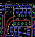
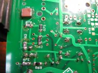
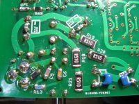
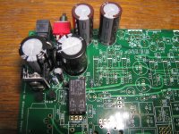
I just found a screw-up. 🙂 Luckily it is easy to correct. In the picture below R10 and R15 are the surface-mount resistor pads for the lowest gain switch position. I have that lowest position defaulting to 1x (or 1/2x if the attenuation resistors are used). In the BOM I have those resistors listed as 15K.
If you are using 1x gain those pads should actually be unpopulated - remove the 15K resistors if you have soldered them in. A super easy way to do it is place a piece of copper desoldering wick on top of the 1206 SMD resistor and then heat the braid. It will melt the solder on both ends of the resistor at once.
There doesn't need to be any resistor in that position if the gain is 1x. The stage then defaults to a unity gain voltage follower with the 1.5K feedback resistor on each channel. This is similar to cutting out the gain resistors on NwAvGuy's O2 Headphone Amp for 1x gain. Using the 15K resistor gives a gain of 1.1x rather than 1x. Worse still, it inserts a 15K resistor worth of Johnson noise into the feedback loop in the 1x gain position.
If your chosen lowest gain switch position is something other than 1x then you will need resistors in these two positions, of course.
An update on the V2.1 boards...
They have shipped and now 7 days or so in the mail from China to the US. Pretty amazing they were able to process 30 4-layer boards in just 5 business days.
I've updated the information at the top of the first post in this thread to add V2.1. At the project's Google Drive link in that post there is now a 7_9_2014 V2.1 subfolder where I've started to add sub-folders with layout, schematic, build instructions, etc. I'm going to wait to post the BOM until after the dScope measurements are made, or until after the boards are in and I've built and tested one and am ready to ship boards, whichever comes first. 🙂
This run of boards will be sold at-cost again to help with the DIY effort since minimum board fab quantities are usually 5 boards or more. Info is in the "next board run" folder under the V2.0 section. I'll make a post in my vendor thread in the Vendor Bazaar forum here and send PMs out to everyone on that list when the time comes, after the boards arrrive and I've built and tested one.
Attachments
Last edited:
dScope: the ODA provides 4.4x the O2's power into 15R at 36% lower THD+N
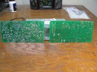
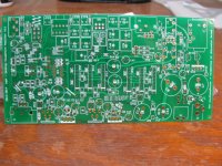
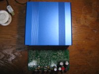
The new V2.1 boards arrived today already! Photos below. Now I'll build one up and test it. 🙂
Well a big "thank you" goes out to mgalusha at AudioCircle.com for his dScope tests on the ODA headamp - and to adydula for making the introduction! Mike has created a precision load box to use with the dScope testing with 1K, 5W, 10 turn pots to very closely match the loads on the two channels. I really appreciate his efforts. Setting up and running tests like this takes a huge amount of time and effort.
His dScope tests are ongoing, but I have at least one result to share so far that makes me pretty happy. In NwAvGuy's blog of his O2 headphone amp dScope test results here:
NwAvGuy: O2 Headphone Amp
search down for the heading "THD+N vs. OUTPUT & MAX POWER ON AC". In the graph there NwAvGuys shows the dScope THD+N percentages on the Y axis vs. RMS output voltages on the X axis, for several different output loads on the O2 headamp. The yellow curve shows that the O2's maximum output power, while on AC, for a 15R load (before severe distortion sets in due to clipping) is around 2.0Vrms at 0.0032% THD+N. That point is 266mW into the 15R load [(2Vrms^2 / 15R]. Going slightly above that output level for the O2 headamp the graph shows that the distortion shoots up to 1% at 2.2Vrms (366mW) with the onset of clipping.
So the maximum "clean" power NwAvGuy's O2 headphone amp can deliver to a 15R load is around 2.0Vrms, at 0.0032%THD. The ODA is capable of delivering many times more power into a 15R load, but the big question has been at what THD+N levels.
At a power level into the 15R load of 293mW, which is close to the O2's maximum "clean" 15R load power level from above, Mike's dScope measured a THD+N of 0.00207% for the ODA on one channel. The other channel measured 0.00203% with a power level of 283mW. Those THD+N numbers are about 36% less than the O2 headamp. The dScope is calculating the power output levels based on Mike entering 15R loads into the dScope setup screens. He measured those precision 1K, 5W, 10 turn pots for the output load to differ by only 0.05R from channel to channel.
The going up from there, which the O2 headamp can't do since it is maxed out at the 266mW, Mike cranked the ODA headamp up to an output power level of 1.17W into the 15R load. This is about 1.17W/0.266W = 4.4x more power than the O2 can deliver to a 15R load. Here his dScope measured a THD+N of 0.00201%, almost identical to the THD+N level at 283mW before, and still 36% less than the O2's THD+N level at its maximum "clean" output into 15R. The other channel tested very similar.
Going up further from there the ODA can crank out more power still, but his dScope showed the distortion rising a bit. He found the ODA's maximum "clean" output level into 15R, before a significant rise in THD+N (which indicates clipping, of course) was around 1.68W with a THD+N of 0.01232%. The other channel measured 1.6722W into 15R with THD+N at 0.00723%. The ODA will go slightly higher in output power, but the THD+N then shoots up dramatically (the start of clipping) as the dScope readings showed.
The difference in THD+N in the two channels is likely due to me sending Mike an ODA that has 0.5R balancing resistors on one channel and 2R resistors on the other channel. This seemed like a good opportunity to explore the effects of the parallel op amp balancing resistors on THD+N.
So that maximum ODA output level of 1.7W into 15R is 1.67W/0.266mW = 6.3 times the maximum power output of the O2 into 15R. The ODA power output level into 15R that would match the O2's 0.0032% THD+N at its maximum level would then be somewhere between the 1.17W and the 1.7W output levels, maybe somewhere around 1.4W or so, about 5X the O2's maximum 15R power level.
The results are what I was hoping for! One of the major design goals of the ODA was the ability to supply significantly more power into low impedance loads, for low-impedance low-sensitivity cans like the HE6 and HE500, than NwAvGuy's O2 headphone amp is capable of. And the hope was that it woild be able to do that at least as cleanly, in terms of THD+N, as the O2 and maybe just a bit more. It looks like that particular design goal has been met! 🙂
I am going to post all the "bad stuff" that crops up in the dScope testing as well as any "good stuff", like this particular measurement happened to be. No cherry picking on measurements. 🙂 That is where helpful design changes come from. Already the testing led me to discover that error of including the 15K gain setting resistors, as I posted about previously.
Again a huge "thank you" goes out to Mike for the dScope testing work! I will post a link to the dScope shots and/or video when the testing is all completed.
I also wanted to give a big thank you to John at JDS Labs for his offer to dScope test the ODA. I was going to take him up on that, but when the opportunity came up for someone in the DIY community (non commercial) to do the testing I went with that, in the spirit of NwAvGuy's original testing. Thanks John!
And finally the biggest "thanks" of all goes to NwAvGuy of course, for his work in creating the O2 headamp in the first place. I know that one of his posted concerrns in his blog was to "not mess up a good thing" in terms of the O2's measurements. Hopefully that ODA will meet that goal, at least in the majority of areas.
Attachments
Last edited:
agdr, I'm pretty sure you're forgetting yourself in that round of thanks.
Those numbers are amazing. The HE-6 is the only headphone I can think of I'd put so much power through, and even then only for very short listening sessions.
Still no reply from Eagle yet, if they don't reply for another week or two it may be worth just ringing up and asking to speak to someone higher up.
Moragg - thanks! It is just fantastic to be able to see the actual objective measured THD+N numbers. Up until now I've had to go by what should happen based on the design and whatever the QA400 analyzer (soundcard in a box) could show.
I think there are one or two freeway layout editors out there like KiCad. If I ever go for a larger design one of these days those might be an option, although it would mean re-doing a bunch of library parts.
I think there are one or two freeway layout editors out there like KiCad. If I ever go for a larger design one of these days those might be an option, although it would mean re-doing a bunch of library parts.
I know once all the design goals (from a measurement perspective) are met I'll be very tempted to get an ODA immediately.
With regards to the crossfeed I found this monster of an amp: SPL Phonitor 2 - all I can say is wow at the sheer size and number of options it has.
A legally binding agreement not to profit off a PCB made on the Pro CADSoft version (without paying for the upgrade in full) should be fine by them, but the hassle factor of getting it cleared is the only thing stopping that being a possibility.
If you do go for a larger PCB and custom case I think it may be worth doing it all split board - bottom could contain the "core" amp + power filter, top could have all the extras + room for ODAC. Size-wise that makes sense as LincolnBinns did suggest moving to a 66mm height case and that'd look better than having a doubly long or wide case.
A friend took my HD800s and my Mayflower O2/dac and claims to be able to hear noise without the gain switch, with the volume knob at 30% (Windows volume @ 100%). Based on past experience this friend's tastes in audio and hearing is... controversial. So I'm not sure if he is BSing me or this is actually a thing.
And if there is audible noise, do you think it's the fault of Mayflower assembling the thing or Nwavguy's O2 simply not good enough? And if the latter, do you figure the ODA will cut it?
And how has the progress been on the ODA in the past half a year? Anything interesting happen? Any good news for people that can't DIY this stuff to save his or her life?
With regards to the crossfeed I found this monster of an amp: SPL Phonitor 2 - all I can say is wow at the sheer size and number of options it has.
I've looked at that Phonitor before and it does have an impressive array of features. $2,000 though! 😱
I agree, there is a lot of merit to a split board approach.🙂
And if there is audible noise, do you think it's the fault of Mayflower assembling the thing or Nwavguy's O2 simply not good enough? And if the latter, do you figure the ODA will cut it?
And how has the progress been on the ODA in the past half a year? Anything interesting happen? Any good news for people that can't DIY this stuff to save his or her life?
The O2 itself if pretty noise-free, although I can hear a tiny amount of background hiss if I turn the gain and volume all the way up and use sensitive headphones. For larger amounts of noise I would suggest taking a look at the build - especially wire routing. Maybe the ODAC has a problem.
The V2.1 ODA boards have arrived and I'm building one up now. 🙂 Also finally have some dScope measurements thanks to mgalusha at Audio Circle. The ODA is still all DIY though. I set up a website with an assembled one listed, but everyone got sticker shock when the labor was added. I've given up on that. Best thing there is to try to locate a DIY'er who is comfortable with the surface mount soldering to build one up. If any of the folks who have built an ODA so far are interested in something like that, an ODA build service, you might want to make a post over in the Vendor Bazaar forum to let folks know.
Last edited:
The O2 itself if pretty noise-free, although I can hear a tiny amount of background hiss if I turn the gain and volume all the way up and use sensitive headphones. For larger amounts of noise I would suggest taking a look at the build - especially wire routing. Maybe the ODAC has a problem.
The V2.1 ODA boards have arrived and I'm building one up now. 🙂 Also finally have some dScope measurements thanks to mgalusha at Audio Circle. The ODA is still all DIY though. I set up a website with an assembled one listed, but everyone got sticker shock when the labor was added. I've given up on that. Best thing there is to try to locate a DIY'er who is comfortable with the surface mount soldering to build one up. If any of the folks who have built an ODA so far are interested in something like that, an ODA build service, you might want to make a post over in the Vendor Bazaar forum to let folks know.
I have set the playback mode in Control panel -> Audio hardware -> Odac properties -> Advanced from 16bit 44khz to 24bit 96khz and that SOMEHOW solved the hissing. I don't understand why. It just does though. Although, the hissing problem I was getting will not be audible under normal operating conditions. Gunning the volume to a level that would hurt my ears within 10 seconds is not 'normal operation'. And the two headphones I see myself having are HD800s and LCD-X, neither of which requires the volume to be high at all.
How difficult do you think the ODA is to assemble? I have no experience with this stuff at all. I have a friend that knows how to solder, that's basically it. I mean, I don't want to bork everything trying to build it and have to try again. It's nice to learn stuff, building something like this, but only with somebody who knows what the hell we're doing. 😀
You know what would be nice? If you made a changelog. So, you add the version number, date the change was added, and exactly what change each revision adds. Personally I love reading changelogs for some reason.
And so, I heard the ODA is capable of powering the HE-6, and also allows for two headphones to be plugged in? (Going off of what I was told in some other forum - My brain is pretty hazy right now.) So does it power both at the same time or is there a way to switch between them?
I too would like to try my hand at soldering, but from what I see surface mounted components can be a bit tricky to work with. Again, if we could get large board sizes it'd probably be possible to make everything soldered, as iirc they're only surface-mount to save space.
Darkwizzie - as of right now both are powered simultaneously. I did consider suggesting a switch for AB testing but when you have to change the headphones on your head anyway I felt it was kind of pointless. Far more useful would be if both plugs were 6.3mm sockets and both had individual volume control. That would allow for volume-matching during comparisons, or for individual volume control if having 2 people using headphones, and it's a lot easier to use 6.3mm to 3.5mm adapters than the other way around.
If (when!) commercialised I could this feature selling really well to audiophiles - an O2 with loads moar powah and letting them compare their headphones side by side.
I just wonder how much it'd cost. The O2/dac combo with quarter inch jack is $300+ already.I too would like to try my hand at soldering, but from what I see surface mounted components can be a bit tricky to work with. Again, if we could get large board sizes it'd probably be possible to make everything soldered, as iirc they're only surface-mount to save space.
Darkwizzie - as of right now both are powered simultaneously. I did consider suggesting a switch for AB testing but when you have to change the headphones on your head anyway I felt it was kind of pointless. Far more useful would be if both plugs were 6.3mm sockets and both had individual volume control. That would allow for volume-matching during comparisons, or for individual volume control if having 2 people using headphones, and it's a lot easier to use 6.3mm to 3.5mm adapters than the other way around.
If (when!) commercialised I could this feature selling really well to audiophiles - an O2 with loads moar powah and letting them compare their headphones side by side.
BTW, Moragg.
You seem slightly familiar to me. 😛
dScope: ODA powerline harmonics levels & 2-board option
More helpful information from the dScope test results. 🙂 This time on residual powerline harmonics vs. NwAvGuy's published dScope powerline harmonics measurements on AC for his O2 headphone amplifier.
The ODA has the same or slightly higher powerline harmonics than the O2 up through the 6th harmonic, then lower harmonic levels for the outer 7th - 9th harmonics. The slightly larger numbers on the first few harmonics are likely due to the larger AC power supply section and proximity to the amp. All the measured ODA powerline harmonic levels should still be way below hearing threshold.
I was going to drop the 2-board option (in the V2.0 build instructions) with the longer B4-160 case from the V2.1 build instructions, but now it is back. 😀 Putting additional spacing between the AC section of the power supply and the rest of the amp should help significanly lower the powerline harmonic levels. One could argue that fits in with the concept of a desktop headphone amp in that the desktop amp has the luxury of using a bigger box vs. a portable, like the O2 headamp.
Note that none of the dScope measured ODA powerline harmonic levels are a problem in any way, all should be below hearing levels as per NwAvGuy's "-94dB" comment below. The 2 board option is just for those folks that want to go the extra mile and try to more significantly beat the O2 in some of the numbers.
In NwAvGuy's O2 headphone amplifier blog here
NwAvGuy: O2 Headphone Amp
search for the title "THD+N 15 OHMS SPECTRUM". There he shows the 60Hz powerline fundamental at about -120dB, the 120Hz powerline 2nd harmonic at around -135dB, the 3rd 180Hz at 120dB, the 4th 240Hz at -125dB, the 5th 300Hz at -122dB, the 6th 360Hz at -135dB, and the 7th 420Hz at -125dB. Note that on the right part of that graph the 2nd harmonic from the 1Khz test signal in the O2 is at -95dB at 2Khz and the 3rd harmonic is at -105dB at 3Khz, with NwAvGuy considering both of those levels just fine. "...everything well below an impressive -94dB" he wrote. in the text above that graph.
The dScope readings on the V2.0 ODA board measured:
* -120dB for the 60Hz powerline fundamental on one channel, same as the O2, but -100dB on the other channel which is 20dB more than the O2. Luckily -100dB is still quite low and shouldn't be audible. The channel with the higher 60Hz is the one with the output chips closer to the AC power supply section.
* -120dB for the 120Hz powerline 2nd harmonic on both channels, about 15dB more than the O2, but should be inaudible at -120dB.
* -120dB for the 180Hz 3rd harmonic on both channels, same as the O2.
* -120dB for the 240Hz 4th harmonic on both channels, 5dB more than the O2, but should be inaudible at -120dB.
* -120dB for the 300Hz 5th harmonic on both channels, 3dB more than the O2, but should be inaudible at -120dB.
* -125dB for the 6th harmonic on both channels, 10dB more than the O2, but should be inaudible at -125dB.
* -130dB for the 7th harmonic on both channels, 5dB less than the O2.
The subsequent ODA powerline harmonics 8th and out are all at or below -140dB on both channels. That beats the O2 on the first few with its 8th at -132dB, 9th at -128dB, and 10th at -130dB.
The 2 board build option just uses 2 ODA boards end-to-end in the bottom slot. Only the power supply and relay circuit parts (and rear RCA jack) are populated on the back board. Everything but those parts are populated on the front board. The the power supply output in the back board is cabled to the amp power input on the front board. The rear RCA jack cables to the same holes on the front board (or the holes by the 3.5mm input jack) with two audio coax cables. And then one single wire connects the output of the relay circuit on the back board to the relay coil on the front board.
Using the two board option will require a bit more DIY skill to wade through the instructions and run those 6 wires between the two boards. But the net result will be putting about 60mm of additional spacing between the AC parts and the amplifier parts. I'm going to build up a power supply only board and test the result at least on by QA400 tester.
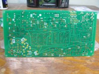
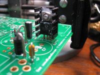
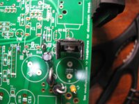
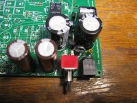
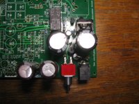
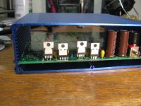
In other ODA news, below are some pictures of the power input section on the V2.1 board built up. Note the new larger PCB-pin mount heatsink on IC11, the 4.7uF relay timing capacitor now under the 1.4" jack as surface mount, and the new fuse. Also shown are the new 0.01uF ceramic capacitors across C11 & C12 (leaded parts) and C7 & C8 (through hole) on the bottom of the board.
D17, what was to be the new line transient absorber, is the first mistake I've discovered. 🙂 I had a brain hiccup somewhere along the way and specified a unidirectional part rather than bi-directional - and bi-directional is a different package size. So D17 will be left off the build and BOM (even though it shows soldered in here).
The whole pile of build photos will be posted on the project's V2.1 Google Drive. The steps are so similar to V2.0's photo build posted on the forum here that I will just include some text files there about the differences.
More helpful information from the dScope test results. 🙂 This time on residual powerline harmonics vs. NwAvGuy's published dScope powerline harmonics measurements on AC for his O2 headphone amplifier.
The ODA has the same or slightly higher powerline harmonics than the O2 up through the 6th harmonic, then lower harmonic levels for the outer 7th - 9th harmonics. The slightly larger numbers on the first few harmonics are likely due to the larger AC power supply section and proximity to the amp. All the measured ODA powerline harmonic levels should still be way below hearing threshold.
I was going to drop the 2-board option (in the V2.0 build instructions) with the longer B4-160 case from the V2.1 build instructions, but now it is back. 😀 Putting additional spacing between the AC section of the power supply and the rest of the amp should help significanly lower the powerline harmonic levels. One could argue that fits in with the concept of a desktop headphone amp in that the desktop amp has the luxury of using a bigger box vs. a portable, like the O2 headamp.
Note that none of the dScope measured ODA powerline harmonic levels are a problem in any way, all should be below hearing levels as per NwAvGuy's "-94dB" comment below. The 2 board option is just for those folks that want to go the extra mile and try to more significantly beat the O2 in some of the numbers.
In NwAvGuy's O2 headphone amplifier blog here
NwAvGuy: O2 Headphone Amp
search for the title "THD+N 15 OHMS SPECTRUM". There he shows the 60Hz powerline fundamental at about -120dB, the 120Hz powerline 2nd harmonic at around -135dB, the 3rd 180Hz at 120dB, the 4th 240Hz at -125dB, the 5th 300Hz at -122dB, the 6th 360Hz at -135dB, and the 7th 420Hz at -125dB. Note that on the right part of that graph the 2nd harmonic from the 1Khz test signal in the O2 is at -95dB at 2Khz and the 3rd harmonic is at -105dB at 3Khz, with NwAvGuy considering both of those levels just fine. "...everything well below an impressive -94dB" he wrote. in the text above that graph.
The dScope readings on the V2.0 ODA board measured:
* -120dB for the 60Hz powerline fundamental on one channel, same as the O2, but -100dB on the other channel which is 20dB more than the O2. Luckily -100dB is still quite low and shouldn't be audible. The channel with the higher 60Hz is the one with the output chips closer to the AC power supply section.
* -120dB for the 120Hz powerline 2nd harmonic on both channels, about 15dB more than the O2, but should be inaudible at -120dB.
* -120dB for the 180Hz 3rd harmonic on both channels, same as the O2.
* -120dB for the 240Hz 4th harmonic on both channels, 5dB more than the O2, but should be inaudible at -120dB.
* -120dB for the 300Hz 5th harmonic on both channels, 3dB more than the O2, but should be inaudible at -120dB.
* -125dB for the 6th harmonic on both channels, 10dB more than the O2, but should be inaudible at -125dB.
* -130dB for the 7th harmonic on both channels, 5dB less than the O2.
The subsequent ODA powerline harmonics 8th and out are all at or below -140dB on both channels. That beats the O2 on the first few with its 8th at -132dB, 9th at -128dB, and 10th at -130dB.
The 2 board build option just uses 2 ODA boards end-to-end in the bottom slot. Only the power supply and relay circuit parts (and rear RCA jack) are populated on the back board. Everything but those parts are populated on the front board. The the power supply output in the back board is cabled to the amp power input on the front board. The rear RCA jack cables to the same holes on the front board (or the holes by the 3.5mm input jack) with two audio coax cables. And then one single wire connects the output of the relay circuit on the back board to the relay coil on the front board.
Using the two board option will require a bit more DIY skill to wade through the instructions and run those 6 wires between the two boards. But the net result will be putting about 60mm of additional spacing between the AC parts and the amplifier parts. I'm going to build up a power supply only board and test the result at least on by QA400 tester.
In other ODA news, below are some pictures of the power input section on the V2.1 board built up. Note the new larger PCB-pin mount heatsink on IC11, the 4.7uF relay timing capacitor now under the 1.4" jack as surface mount, and the new fuse. Also shown are the new 0.01uF ceramic capacitors across C11 & C12 (leaded parts) and C7 & C8 (through hole) on the bottom of the board.
D17, what was to be the new line transient absorber, is the first mistake I've discovered. 🙂 I had a brain hiccup somewhere along the way and specified a unidirectional part rather than bi-directional - and bi-directional is a different package size. So D17 will be left off the build and BOM (even though it shows soldered in here).
The whole pile of build photos will be posted on the project's V2.1 Google Drive. The steps are so similar to V2.0's photo build posted on the forum here that I will just include some text files there about the differences.
Attachments
Last edited:
I can't see too many people opting to double the size just to improve some already good enough numbers, though with that said if it were possible to rearrange components to keep the AC power supply section (or at least the offending bits of it) further away from the amp.
If you can measure (since I don't have a PCB) what is the difference in "distance from AC" for the output chips for L+R channels? It may be that just a cm or two are needed to beat the O2 - while I wouldn't chase numbers for no reason, it'd be a shame not to beat it in every aspect if it were very cheaply (and practically) possible.
My perhaps "main" worry would be that the power supply is naturally in the back, like the ODAC would be if installed - could the effect of the power section on the ODAC noticeably reduce it's performance?
I can't see too many people opting to double the size just to improve some already good enough numbers
Good point, since at -100dB the "worst" poweline harmonic should still be way below hearing level. The 2 board build and longer case would be purely for better measurements that in all likelyhood are inaudible.
If you can measure (since I don't have a PCB) what is the difference in "distance from AC" for the output chips for L+R channels? It may be that just a cm or two are needed to beat the O2 - while I wouldn't chase numbers for no reason, it'd be a shame not to beat it in every aspect if it were very cheaply (and practically) possible.
You are right, E and B field strength are square law things, so moving the parts a certain distance further away should cause the field strengh to drop by the square of the additional distance. A small bit of extra spacing can go a long way to helping reduce radiated EMI. Moving the power supply to the back board *should* drop the EMI considerably if radiated EMI is the cause, but things can be tricky. There can be internal reflections inside the metal box. In a commercial unit there would likely be a shielded & grounded metal cage around the power supply parts.
My perhaps "main" worry would be that the power supply is naturally in the back, like the ODAC would be if installed - could the effect of the power section on the ODAC noticeably reduce it's performance?
There is definitely a chance of that if digital noise gets into the analog parts. With the ODAC mounted on a top slot board I'm expecting there won't be a problem, but that configuration (with the internal ODAC) really needs to be dScoped too. I should go back and read through NwAvGuy's blog again about the ODAC. I can't recall him ever running another noise floor test on the combination ODAC +O2.
If a commercialised version had a Faraday cage around the power supply bit the ODAC should also escape from the interference, shouldn't it? I wonder how hard/expensive this would be though...
On OCN someone asked about using the O2 for the HE-6, and after running though the numbers I couldn't see why that'd be a problem - it should just about manage 105dB. This is because the "actual" HE-6 sensitivity is lower than HiFiMan state - Tyll measured it at 77dB SPL/1mW - which is a huge 6.5dB lower than the company say.
This means the HE-6 would need 2W to hit 110dB - or 0.2A @ 10V.
At 7.25V max Vrms into 50R there's "only" 1W of current, so 107dB.
What I'm having trouble understanding is why, then, are there 6 current buffers when 4 would work just fine (apart from it being really cheap)?
Electrically I don't know why this isn't the case, but would it not be better to change/have more gain-stage opamps so that 10V can be reached for all headphone impedances? This would benefit both the HE-6 and the high-impedance dynamic headphones needing it.
The HE-6 being far less efficient than stated is a pain - it makes meeting the ODA's goal of driving all headphones (save for electrostatics) a lot harder.
B4-160 case and the 2-board build option
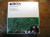
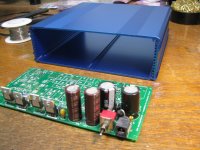
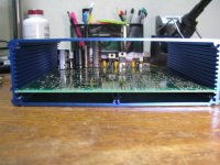
I received one of the longer B4-160 Box Enclosures cases today for the 2-board option. Below are some pictures of how it looks. At Allied Electronics the B4-160 case is about $10 more than the B4-080 case.Two ODA boards fit end-to-end. The ODA board in the photo is one I'm building up specifically to be the "rear board" in a two board build. The parts shown in the photo are pretty much all it will have, just the power supply and relay sections. This one still needs the rear RCA jack and the relay circuit (minus the relay itself) added.
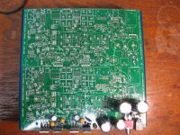
* The next photo shows the rear board and a blank board end-to-end on the top of the box. That "front" board will have all the parts populated except the parts on the rear board (power supply, relay circuit, rear RCA jack). In my case for testing purposes I'm going to use a fully populated ODA board for the front board, I'll just un-jumper the power disconnects, JP18 & JP19, and instead feed the power from the rear ODA board.
The six wires needed to connect the two boards are
1) ground, V+, and V- between the two boards. So any of the 4 holes in the rear board JP6 ground connection to any of the 4 holes in the front board JP6. Either of the bottom two JP18 V+ rail feed holes in the rear board to either of the top two JP18 V+ connection holes in the front board. Either of the bottom two JP19 V- rail feed holes in the rear board to either of the top two JP19 V- connection holes in the front board. All three wires should be twisted together.
2) two audio coaxial cables going from the rear RCA jack pins JP1 to exactly the same holes in the front board JP1. The front board won't have the rear RCA jack installed of course. I will probably also include instructions on how to cut the traces going from JP1 on the rear board (easy to do). That will remove the extra trace length along the left side that would normally connect the rear RCA jack to the input select switch, which would help eliminate any noise pickup.
3) one wire going from the relay out circuit on the rear board to the relay on the front board. The relay circuit is relative to the V- rail, so the other half of the relay connection gets made automatically when you connect the V- rail.
* The last two photos are front and back shots with both ODA board in the second slot up from the bottom end-to-end.
I received one of the longer B4-160 Box Enclosures cases today for the 2-board option. Below are some pictures of how it looks. At Allied Electronics the B4-160 case is about $10 more than the B4-080 case.Two ODA boards fit end-to-end. The ODA board in the photo is one I'm building up specifically to be the "rear board" in a two board build. The parts shown in the photo are pretty much all it will have, just the power supply and relay sections. This one still needs the rear RCA jack and the relay circuit (minus the relay itself) added.
* The next photo shows the rear board and a blank board end-to-end on the top of the box. That "front" board will have all the parts populated except the parts on the rear board (power supply, relay circuit, rear RCA jack). In my case for testing purposes I'm going to use a fully populated ODA board for the front board, I'll just un-jumper the power disconnects, JP18 & JP19, and instead feed the power from the rear ODA board.
The six wires needed to connect the two boards are
1) ground, V+, and V- between the two boards. So any of the 4 holes in the rear board JP6 ground connection to any of the 4 holes in the front board JP6. Either of the bottom two JP18 V+ rail feed holes in the rear board to either of the top two JP18 V+ connection holes in the front board. Either of the bottom two JP19 V- rail feed holes in the rear board to either of the top two JP19 V- connection holes in the front board. All three wires should be twisted together.
2) two audio coaxial cables going from the rear RCA jack pins JP1 to exactly the same holes in the front board JP1. The front board won't have the rear RCA jack installed of course. I will probably also include instructions on how to cut the traces going from JP1 on the rear board (easy to do). That will remove the extra trace length along the left side that would normally connect the rear RCA jack to the input select switch, which would help eliminate any noise pickup.
3) one wire going from the relay out circuit on the rear board to the relay on the front board. The relay circuit is relative to the V- rail, so the other half of the relay connection gets made automatically when you connect the V- rail.
* The last two photos are front and back shots with both ODA board in the second slot up from the bottom end-to-end.
Attachments
Last edited:
If a commercialised version had a Faraday cage around the power supply bit the ODAC should also escape from the interference, shouldn't it? I wonder how hard/expensive this would be though...
Yep, the sheilding probably isn't practical for DIY. It all has to be custom made.
On OCN someone asked about using the O2 for the HE-6, and after running though the numbers I couldn't see why that'd be a problem - it should just about manage 105dB. This is because the "actual" HE-6 sensitivity is lower than HiFiMan state - Tyll measured it at 77dB SPL/1mW - which is a huge 6.5dB lower than the company say.
This means the HE-6 would need 2W to hit 110dB - or 0.2A @ 10V.
At 7.25V max Vrms into 50R there's "only" 1W of current, so 107dB.
Yes it will! 😀 A month or so ago I posted all the HE6 and HE500 numbers out on the V2.0 project Google Drive link under the "Headphone types vs. the ODA" folder
https://drive.google.com/folderview?id=0B67cJELZW-i8SXZrcktvTGl2Y28&usp=sharing
These are done on a spreadsheet that had been posted to Head-Fi last year. It calculates the voltage and current needed to hit a certain dB SPL level given a certain headphone impedance and sensitivity.
Even the AKG- K1000 is no problem for the ODA. 🙂 NwAvGuy used that as his "worst case" headphone example, something the O2 just couldn't drive.
What I'm having trouble understanding is why, then, are there 6 current buffers when 4 would work just fine (apart from it being really cheap)?
Electrically I don't know why this isn't the case, but would it not be better to change/have more gain-stage opamps so that 10V can be reached for all headphone impedances? This would benefit both the HE-6 and the high-impedance dynamic headphones needing it.
The HE-6 being far less efficient than stated is a pain - it makes meeting the ODA's goal of driving all headphones (save for electrostatics) a lot harder.
I was thinking of also having the ODA be able to drive small (PC size) bookshelf/desktop speakers, which it probably can. If possible I would also like to get a set of dScope measurements into 8 ohms, something NwAvGuy never attempted with the O2 headamp.
I ran up against a bit of a wall with the NJM4556A output chips. Above +/-12Vdc rails their quiescent current draw starts resulting in power dissipation numbers that consume about 2/3 of the chip's rated power dissipation (at +/-16Vdc rails, which is what I was originally going to have the ODA run at). That is why I have the build split into the two types, with the +/-15Vdc build only for 300R headphones and above. At +/-15Vdc that is all the power dissipation ability left in the output chips with the quiescent power subtracted.
There is another hiccup with the NJM4556A chips buried in the datasheets notes. Even though the chip's power supply can go above +/-15Vdc, the input can't. So some care has to be taken then. Being fed from the LME49990 that is OK since its output stays 2V away from the rails anyway.
The LME49990 chip though could be fed with +/-18Vdc rails with no problem. It is rated for that in 600R, which is what you get in the ODA with the 1K pot in parallel with the 1.5K feedback resistor, and the chip dissipation would be OK even with the quiescent power subtracts (single op amp vs. dual in that package). BUT.. the 1K pot would burn up on maximum output. The 9mm linear is only rated at 50mW, which is exactly what you get with the +/-12.5Vdc rails resulting 7.25Vrms maximum swing. I've looked all over the place at Mouser and Digikey and there don't seem to be any higher rated dual section 1K pots, not even panel mount.
Then there is the problem about what to do with the output chips. The LME49610 is rated up to +/-22Vdc, but those are in the heatsink-problematic TO263 package that would require many square inches of board foil for heatsinking at full power. It would also have to be wrapped in a loop with a LME49990 or other chip. I've been avoiding that with the LME49990 since I don't want to compete with opc's Wire. No point in re-inventing the wheel.
There are not many high(er) voltage op-amp buffer chips out there, so for higher voltage rails I would probably look at a class A or AB discrete transistor design if I ever built something like that. But then it would start looking like AMB's b22 headamp - no point in re-inventing the wheel on that one either.
In the end I decided to stay with the NJM4556A output chips despite the voltage limitations since it could probably be argued to be the "most ODA-like" thing to do as a step-up from the O2 headamp. 🙂
Last edited:
After having a look through all these DIY amps I'm very tempted to design my own. I'm fairly confident if I had a full list of all types of components, their advantages/disadvantages/limitations, and equations I should be able to make something that rivals everything - but that's the mathematician's fallacy 🙂 In college though I should be able to get access to some very good equipment if I ask nicely.
At 7.25Vrms the ODA would have trouble pushing the AKG-K1000 past 100dB... it's an unbelievably low sensitivity headphone.
Do you have any idea how much noise the 1K pot is contributing? If it is negligible compared to noise from elsewhere then you should be able to use a bigger pot without issue.
As for using other's solutions... if you can't come up with a better one then I believe NwAvGuy would've gone for whatever works. If the idea is simple then the designers shouldn't have a problem with you using it - imitation is the best form of flattery after all.
After having a look through all these DIY amps I'm very tempted to design my own.
Hey you should! 🙂
At 7.25Vrms the ODA would have trouble pushing the AKG-K1000 past 100dB... it's an unbelievably low sensitivity headphone.
Yeah like NwAvGuy posted once, "earspeakers".
Do you have any idea how much noise the 1K pot is contributing? If it is negligible compared to noise from elsewhere then you should be able to use a bigger pot without issue.
That is exactly what I've had to do for the +/-15Vdc rail version. It uses the 5k 9mm pot. When the pot value goes up the ground return resistor on the other side of the coupling caps has to go up also to keep from loading the pot, so that goes from 4.99K to 24.5K. Still better (lower Johnson/thermal noise) than the 40.2K resistors in the O2. You are right, that would be another option if bumping the LME49990 gain stage up to +/-18Vdc rails is just go with the a 5K pot. Problem solved.
- Home
- Amplifiers
- Headphone Systems
- A version of an O2 Desktop Amp (ODA)