Herb777.
The 6mm has round flutes with thicker walls, the thinner proplex has square flutes and starts to look more like correx.
Proplex has a strong output down to 40hz with my 10 watt excites, But I need more power to push this panel harder.
The thinner proplex starts to look like correx with much lighter and thinner walls.
The correx is heavy compared to EPS.
My exciters can drive the 4mm proplex ok.
Correx is 3mm.
Steve.
How did 3mm Correx sound?Herb777.
The 6mm has round flutes with thicker walls, the thinner proplex has square flutes and starts to look more like correx.
Proplex has a strong output down to 40hz with my 10 watt excites, But I need more power to push this panel harder.
The thinner proplex starts to look like correx with much lighter and thinner walls.
The correx is heavy compared to EPS.
My exciters can drive the 4mm proplex ok.
Correx is 3mm.
Steve.
How lovely! Well done Danilo!Well, Danilo Herger's 3rd Russian patent RU2744773C1 applied on 10.08.2020, granted on 15.03.2021 mentions Karavashkin "thesis" and the image of the constructed speaker, reminds me of Mescalito speakers.
Herb777
I have used 1 corrugated cardboard on my 6x9 panels with the xo at about 160hz to 20k
Steve.
I have used 1 corrugated cardboard on my 6x9 panels with the xo at about 160hz to 20k
Steve.
It's your standard cardboard but I have added 2 more layers of corrugated paper/ cardboard , I will be adding a final piece reversed ( corrugated part facing out) this will give it the appearance of an old washboard 😄. The size of the panel is 130 cm X 60 cm it has 2 exciters per side one 32 mm and a small 25 mm strategically placed after many listening sessions, ribbon tweeter fills in after 2400 k and is on a L pad so it can be adjusted to taste. Sides are held solid only the top and bottom are free to move.Can you tell more about that cardboard? Thickness, length and breadth, and whether it is a honeycomb one? Thanks.

Interesting!It's your standard cardboard but I have added 2 more layers of corrugated paper/ cardboard , I will be adding a final piece reversed ( corrugated part facing out) this will give it the appearance of an old washboard 😄. The size of the panel is 130 cm X 60 cm it has 2 exciters per side one 32 mm and a small 25 mm strategically placed after many listening sessions, ribbon tweeter fills in after 2400 k and is on a L pad so it can be adjusted to taste. Sides are held solid only the top and bottom are free to move.
When you have time, please post some images, sketches and everything relevant of your build.
I think this stuff comes in different materials some seem pliable while others seem brittle, have you found this? The pliable one if you do the tap test seems a bit flat/ dull while the other one has a bit of ring to it.Herb777.
The 6mm has round flutes with thicker walls, the thinner proplex has square flutes and starts to look more like correx.
Proplex has a strong output down to 40hz with my 10 watt excites, But I need more power to push this panel harder.
The thinner proplex starts to look like correx with much lighter and thinner walls.
The correx is heavy compared to EPS.
My exciters can drive the 4mm proplex ok.
Correx is 3mm.
Steve.
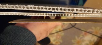
Have you tried the 1mm cardboard? Is that cardboard honeycomb?The picture shows the round and square flutes in the proplex panels, plus the 1mm corrugated cardboard.
The round flute panel is much heavier .
Steve.
Last edited:
Most people mention honeycomb core and a thin film/paper covering it tightly. Honey comb is used to make the panel stiffer, like cardboard. But, the honeycomb panel is used as the DML panel, the honeycomb, not only makes it stiffer, but there are empty spaces in it. Maybe. Göbel considered that and made that perforation in that balsa sheet. What do you think?I noticed that too about the perforations. I don't know exactly what to think of the first picture, where there are no apparent perforations. In fact, it doesn't really even look like end grain balsa. I wonder if that is just a "staged" video clip that didn't use an actual or fully prepared panel for some silly reason. As if they decided they wanted to include a shot of that only after the rest of the video was prepared, and they didn't have any of the right panels handy, so they "faked" it.
There's no reason I can think of that the black spots would be on the fiberglass.
I also don't think the grain direction is different. It's just a bit of balsa thats different in color. Those balsa panels are made of an array of balsa pieces that are perhaps 50mm x75mm glued together on the edges, and not "strips". I don't know for sure, but I suspect they take a bunch of balsa boards that are, say 50mm x75mm x 600mm(?) with the grain running in the long direction. Then they glue them together on the short sides to make a big block and then slice the block into thin panels. That's my best guess anyway.
Eric
That should read 1mm cc, and the answer is yes.Herb777
I have used 1 corrugated cardboard on my 6x9 panels with the xo at about 160hz to 20k
Steve.
Steve.
You can make your own cardboard panel using this corrugated paper but glue the sheets together in opposite directions, one piece horizontal and the next piece vertical. Makes for a stiff board .
Oh, yeah. You could do the same with the proplex or corflute too if you want to reduce the anisotropy. As long as it doesn't get too stiff. Probably you would start with one of the thinner versions in this case.You can make your own cardboard panel using this corrugated paper but glue the sheets together in opposite directions, one piece horizontal and the next piece vertical. Makes for a stiff board .
Eric
I just rememberd one more input / inspiration that I had when building my first version of my flat speaker. It’s a patent by
BENDINGWAVELOUDSPEAKER+
(75) Inventor: HenryAzima,Cambridge(GB)
you might allready have covered this in the thread, I haven’t checked. My apologies in that case.
It’s about moving from a finite panel to infinite panel. My understanding that its very much in line with the göbel design.
It’s dealing with fact that the incident wave induced in the panel is reflected back from the edges with more or less the same energy. You can see the effect in some of the graphs In the patent.
I’ve been struggling with this problem in another bending wave concept ”the walsh speaker” there it’s very clear that the reflected wave is creating distorsion. The walsh speaker is actually working in both modes bending wave and piston As a panel. But the design is a cone instead of flat. I’ve included a picture and the patent for reference.
I’ve also tested to create a border with a stepwise change of the impedence making it more effective to capture the incident wave at the edge.
It’s the huge difference in impedence between air and the panel that causes the reflection.
Attachments
No, I'm pretty sure that's not why the perforations are there (assuming they actually are there). Balsa (especially end grain) is really a lot like honeycomb already (light with decent shear stiffness). In the Goebel panel they aren't really even holes in the end, but rather filled with epoxy.Most people mention honeycomb core and a thin film/paper covering it tightly. Honey comb is used to make the panel stiffer, like cardboard. But, the honeycomb panel is used as the DML panel, the honeycomb, not only makes it stiffer, but there are empty spaces in it. Maybe. Göbel considered that and made that perforation in that balsa sheet. What do you think?
Just to clarify an important point, that may or may not be clear to all. It's not exactly true that the honeycomb makes it stiffer. It is kind of true, but not exactly. What I mean is this, what makes a stiff sandwich structure is (a) stiff skin layers that are (b) separated by a significant distance and (c) both skins attached to a core between them that resists shearing across it's thickness. Shearing deformation is depicted here:
So a honeycomb does make for a stiff composite in that it separates the stiff paper or carbon fiber or fiberglass layers and has just enough shear stiffness.
But what honeycomb really does is make the stiff sandwich panel lightweight. Any rigid core material between the skins would make a sandwich panel that's as stiff (or stiffer) than the same panel with a honeycomb core of the same thckness. But the panel with the honeycomb core would be much lighter.
Eric
Thomas,I’ve also tested to create a border with a stepwise change of the impedence making it more effective to capture the incident wave at the edge.
It’s the huge difference in impedence between air and the panel that causes the reflection.
I'd be very interested to hear the details of your stepwise impedence change. I've been thinking along those lines too but have not tried anything yet.
Eric
Honeycomb makes the composite panel stiff enough to carry a good load on its surface, while being very thin, which is its main asset. But, when you make certain enclosed, or semi enclosed thin walled vertical structures with those composites, they'd carry lot of weight. In our case, the honeycomb panel is fixed, one way or another on the perimeter, shear deformation will not happen. The exciter is actually acts on the stiffer surface perpendicularly. The so-called transverse bending waves are so tiny that they won't break the sheet.No, I'm pretty sure that's not why the perforations are there (assuming they actually are there). Balsa (especially end grain) is really a lot like honeycomb already (light with decent shear stiffness). In the Goebel panel they aren't really even holes in the end, but rather filled with epoxy.
Just to clarify an important point, that may or may not be clear to all. It's not exactly true that the honeycomb makes it stiffer. It is kind of true, but not exactly. What I mean is this, what makes a stiff sandwich structure is (a) stiff skin layers that are (b) separated by a significant distance and (c) both skins attached to a core between them that resists shearing across it's thickness. Shearing deformation is depicted here:
View attachment 1129452
So a honeycomb does make for a stiff composite in that it separates the stiff paper or carbon fiber or fiberglass layers and has just enough shear stiffness.
But what honeycomb really does is make the stiff sandwich panel lightweight. Any rigid core material between the skins would make a sandwich panel that's as stiff (or stiffer) than the same panel with a honeycomb core of the same thckness. But the panel with the honeycomb core would be much lighter.
Eric
I don’t understand this. AFAIK, a stepwise impedance change is what causes reflections in the first place. A smooth impedance change allows minimal reflection, no? This is the principle of impedance matching in electric theory or transmission line theory - to prevent reflections. And principle used in acoustic black hole edge treatment.Thomas,
I'd be very interested to hear the details of your stepwise impedence change. I've been thinking along those lines too but have not tried anything yet.
Eric
Or are you talking about something akin to a quarter-wave optical coating?
This is how you made it. 🙂I just rememberd one more input / inspiration that I had when building my first version of my flat speaker. It’s a patent by
BENDINGWAVELOUDSPEAKER+
(75) Inventor: HenryAzima,Cambridge(GB)
you might allready have covered this in the thread, I haven’t checked. My apologies in that case.
It’s about moving from a finite panel to infinite panel. My understanding that its very much in line with the göbel design.
It’s dealing with fact that the incident wave induced in the panel is reflected back from the edges with more or less the same energy. You can see the effect in some of the graphs In the patent.
I’ve been struggling with this problem in another bending wave concept ”the walsh speaker” there it’s very clear that the reflected wave is creating distorsion. The walsh speaker is actually working in both modes bending wave and piston As a panel. But the design is a cone instead of flat. I’ve included a picture and the patent for reference.
I’ve also tested to create a border with a stepwise change of the impedence making it more effective to capture the incident wave at the edge.
It’s the huge difference in impedence between air and the panel that causes the reflection.
View attachment 1129450View attachment 1129454
- Home
- Loudspeakers
- Full Range
- A Study of DMLs as a Full Range Speaker