This is not free air they’re talking about. Are you proposing to embed the listener into a metamaterial lattice in their living room? Talk about the hard-sell. 🤣Take the blinders off your brains https://www.nature.com/articles/s41467-021-26375-9
I wasn't ignoring your request. Just took some time to get to it.@Veleric
A repeat request.
Can you give links to your DML builds in this thread, Eric? I'd like to read your experiences. Thanks!
I started with MLTLs and did this one using the Mark Audio Alpair 10.3 drivers.
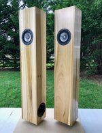
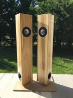
My first DML: https://www.diyaudio.com/community/posts/5978255/
Sadly the images are gone from the link but here are some:
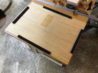
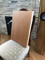
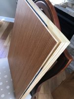
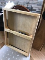
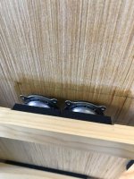
My most recent DML is here, (and in the several posts immediately following)
https://www.diyaudio.com/community/...s-as-a-full-range-speaker.272576/post-7121486
And here is a link that includes a few pictures of the carbon/fiber balsa panels (and frames) that never quite got built (yet).
https://www.diyaudio.com/community/...s-as-a-full-range-speaker.272576/post-7049119
Eric
I assume he's saying he tried to make the steps smaller. I agree a smooth continous change would be best, but several smaller steps might be better than one big one. I assume that was his idea. We'll see what he says.I don’t understand this. AFAIK, a stepwise impedance change is what causes reflections in the first place. A smooth impedance change allows minimal reflection, no? This is the principle of impedance matching in electric theory or transmission line theory - to prevent reflections. And principle used in acoustic black hole edge treatment.
Or are you talking about something akin to a quarter-wave optical coating?
Eric
The problem I had was to find an absorbing material with a impedance that matched the impedance of the carbon fibre panel. After doing some research I found a solution they used in ultra sonic diagnosis where that have problem of matching the impedance of the piezo electric exciter and the human body.I don’t understand this. AFAIK, a stepwise impedance change is what causes reflections in the first place. A smooth impedance change allows minimal reflection, no? This is the principle of impedance matching in electric theory or transmission line theory - to prevent reflections. And principle used in acoustic black hole edge treatment.
Or are you talking about something akin to a quarter-wave optical coating?
They had a lyered approch with stepwise matching. Obviously there are some reflections in each step.
I accept that my idea might be flawed.
mechanical impedence matching lecture.
Thank you for the links. I've been away from this thread for nearly a year, so must've missed them. I'll be reading your posts from #5,825 onwards.I wasn't ignoring your request. Just took some time to get to it.
I started with MLTLs and did this one using the Mark Audio Alpair 10.3 drivers.
View attachment 1129460 View attachment 1129461
My first DML: https://www.diyaudio.com/community/posts/5978255/
Sadly the images are gone from the link but here are some:
View attachment 1129469 View attachment 1129470 View attachment 1129471 View attachment 1129472 View attachment 1129473
My most recent DML is here, (and in the several posts immediately following)
https://www.diyaudio.com/community/...s-as-a-full-range-speaker.272576/post-7121486
And here is a link that includes a few pictures of the carbon/fiber balsa panels (and frames) that never quite got built (yet).
https://www.diyaudio.com/community/...s-as-a-full-range-speaker.272576/post-7049119
Eric
Honeycomb makes the composite panel stiff enough to carry a good load on its surface, while being very thin, which is its main asset. But, when you make certain enclosed, or semi enclosed thin walled vertical structures with those composites, they'd carry lot of weight. In our case, the honeycomb panel is fixed, one way or another on the perimeter, shear deformation will not happen. The exciter is actually acts on the stiffer surface perpendicularly. The so-called transverse bending waves are so tiny that they won't break the sheet.
I'm not sure I understand what you are trying to say, but here's a good explantion of what honeycomb does:
https://www.addcomposites.com/post/sandwich-structures-and-cores
Thanks for the link. I know about sandwich panels. Mostly in construction. Didn't think of them as an audio device, until I joined this thread. 🙂I'm not sure I understand what you are trying to say, but here's a good explantion of what honeycomb does:
https://www.addcomposites.com/post/sandwich-structures-and-cores
Nice link. Where I have trouble is understanding is exactly what would constitute a match for plate and a boundary condition.The problem I had was to find an absorbing material with a impedance that matched the impedance of the carbon fibre panel. After doing some research I found a solution they used in ultra sonic diagnosis where that have problem of matching the impedance of the piezo electric exciter and the human body.
They had a lyered approch with stepwise matching. Obviously there are some reflections in each step.
I accept that my idea might be flawed.
mechanical impedence matching lecture.
For a plate, an approximation for impedence is 8*(B*mu)^1/2. How would I calculate the impedance of my foam boundary (assuming I know it's basic properties?
Eric
Some thoughts on the black art of damping:Nice link. Where I have trouble is understanding is exactly what would constitute a match for plate and a boundary condition.
For a plate, an approximation for impedence is 8*(B*mu)^1/2. How would I calculate the impedance of my foam boundary (assuming I know it's basic properties?
Eric
I wonder whether its the right approach to have a dedicated damping at a boundary.
There are only a few ways for energy to leave the panel:
- Conversion to heat via damping
- As sound (this tends to be rather small even best case)
- By conduction to other structures (might be good if you have a large massive structure that does not resonate audibly)
- Maybe by advanced control of the exciter (like active braking)?
But damping is also your friend, because it both smooths the resonant peaks AND raises the average SPL level.
If you are not beginning with an intrinsically highly damped material, I would be looking at applying progressive damping starting at some distance from the exciter position and increasing outward. This gives you more control of damping of different wavelengths, and a larger area over which to absorb the energy. If you manage to steer the energy “into” to a boundary region, then what? You still have to absorb it somehow within a rather smaller area.
I also remember when attempting experiments with attached mass that I could not discern much change with small masses (mainly because of the rudimentary setup). But if you touch the panel with a finger, your large, highly damped mass absorbs a lot of energy. Maybe we could look at something similar in designs - conduction to a (relatively) large distributed mass (either at a point or edge) which is itself embedded in a damping medium.
Last edited:
Paul,If you are not beginning with an intrinsically highly damped material, I would be looking at applying progressive damping starting at some distance from the exciter position and increasing outward. This gives you more control of damping of different wavelengths, and a larger area over which to absorb the energy. If you manage to steer the energy “into” to a boundary region, then what? You still have to absorb it somehow within a rather smaller area.
Maybe like this?
from here:
https://publications.lib.chalmers.se/records/fulltext/61709.pdf
This panel apparently is said to be a paper/polyether foam/paper sandwich with triangular constrained layer damping elements around the perimeter (both sides of the panel).
As highlighted above, the paper says they follow the "Manger transducer principle", but the Manger membrane seems to be much different (and quite unusual as far as I can tell). Maybe they just mean the spirit of the "principle" in the sense of "highly damped" and not in the sense of having copied the actual details of the membrane.
Manger membrane patent here:
https://patentimages.storage.googleapis.com/a7/b1/4d/789675797ef869/US3937905.pdf
And speakers here:
https://mangeraudio.com/en/
Eric
I guess so. The triangles - I assume they randomise/disperse the reflections to minimise standing waves, give a better distribution of frequencies, and help to match the impedance.Paul,
Maybe like this?
To smoothly transition impedance you can accurately machine a profile in thickness in both materials, then glue them together, or (easier) you can interdigitate both materials so that the transition takes place on the X-Y axis rather than the Z.
I'd like to try something similar with 2mm acrylic and EPS. The idea is to mount an exciter to the acrylic and observe the hf response, then estimate by trial and error (or FEM? 🙂) at what radius to begin a transition (with triangles or smooth fingers). Sort of a physical crossover.
I also think panels would benefit from sculpted ribs for a similar reason. I'm thinking of an organic set of ribs which radiating from the central region and branching like a tree as they become thinner, giving a fast, low impedance path for LF, into the larger panel area. This also increases the effective surface area of the panel, giving a long perimeter with have an, er, perimeter.
Or, maybe its a load of bs.which I just made up. Maybe I should try my hand at writing patents 😎
In the case of composites, I was thinking of something simpler, like attaching foam or other damping material around the exciter, thinly at first and becoming thicker towards the outside.
Paul
Last edited:
Bollocks!!! Just dragged this old project up from the hifi dungeon ( bottom of the tool shed) while I add another layer to my cardboard panels, I thought what the hell I've not tried my 32mm exciters on these bookshelf speakers ( get it!)
So attached exciter to the front as this sounds better I found in the past with these panels, slotted in the ribbon tweeter's hooked them up and sat there open-mouthed. Having spent the last hour gluing up my cardboard jobs, which I was very happy with, I can tell you that's where the bollocks moment happened.
To make things worse these are just lent up against the wall no frame, no wire nothing. Now what do I do?
I'll post a video using the same song at the same volume so you can compare and let me know which you prefer.
I guess so. The triangles - I assume they randomise/disperse the reflections to minimise standing waves, give a better distribution of frequencies, and help to match the impedance.
To smoothly transition impedance you can accurately machine a profile in thickness in both materials, then glue them together, or (easier) you can interdigitate both materials so that the transition takes place on the X-Y axis rather than the Z.
I'd like to try something similar with 2mm acrylic and EPS. The idea is to mount an exciter to the acrylic and observe the hf response, then estimate by trial and error (or FEM? 🙂) at what radius to begin a transition (with triangles or smooth fingers). Sort of a physical crossover.
I also think panels would benefit from sculpted ribs for a similar reason. I'm thinking of an organic set of ribs which radiating from the central region and branching like a tree as they become thinner, giving a fast, low impedance path for LF, into the larger panel area. This also increases the effective surface area of the panel, giving a long perimeter with have an, er, perimeter.
Or, maybe its a load of bs.which I just made up. Maybe I should try my hand at writing patents 😎
In the case of composites, I was thinking of something simpler, like attaching foam or other damping material around the exciter, thinly at first and becoming thicker towards the outside.
Paul
If the prevention of discrete reflection modes from the perimeter is a goal, using pentagonal symmetry and perhaps flower petal lobes might be of use? Also, don’t forget about Fibonacci sequence spirals (nautilus snail shell progression) etc.
For example these were OB speakers but maybe shape could be used as DML?

For example these were OB speakers but maybe shape could be used as DML?
I listened to this video on my conventional speakers (Vanguard 2 way bookshelf monitors). This sounds very good. Nice.
Also listened to the second one with ribbon - also very nice. What is membrane material? Looks like paper faced foam core?
Both panels use the ribbon, first panel ( bookshelf) is XPS 20 mm one side covered in bookshelf themed wallpaper , the other panel is stiff cardboard, I'm a bit torn between them at the moment, XPS has slightly better midrange and the cardboard has slightly better bass.I listened to this video on my conventional speakers (Vanguard 2 way bookshelf monitors). This sounds very good. Nice.
Also listened to the second one with ribbon - also very nice. What is membrane material? Looks like paper faced foam core?
... if you want to reduce the anisotropy
Question – is anisotropy necessarily a negative in DML panels?
The reason also for asking is that I might have access to panels used as flooring in aircraft which looks interesting as possible DML panel material. They describe it as follows – “a high strength floor panel made from unidirectional fiberglass reinforced epoxy facings bonded to meta-aramid honeycomb core”. It’s the unidirectional fibers that has me a little concerned here, but I have no idea how anisotropy these panels are. Might not be an issue at all.
PS: Sorry - I see I'm sort of in between other conversations here
Maybe not necessarily. One penalty of low stiffness is low efficiency, but what's the net effect if one direction is extra stiff and the other extra flimsy? Does the stiff direction more than make up for the flimsy direction? I don't know.Question – is anisotropy necessarily a negative in DML panels?
Presumably, having large anisotropy will influence the ideal aspect ratio to use for a panel, as the anisotropy will influence how the modal frequencies "interleave". So if you find a particular aspect ratio that works great for an isotropic panel, I wouldn't expect it to work the same for a strongly anisotropic panel.
Spedge seems to like the Proplex, which I suspect is strongly anisotropic. So apparently it's not a dealbreaker.
Presently I'm preferring panels with slight anisotropy (say 2:1 ish), but that's for a pretty particular case.
Eric
- Home
- Loudspeakers
- Full Range
- A Study of DMLs as a Full Range Speaker