How small can you make C7 in a normal Jfet buffer and not have noise problems?
R22 and R23 are actually part of the RIAA network so I'm not quite sure what you mean. You could tweak the 90.9K resistors in the RIAA and make the gate resistors huge and get away with smaller values. Below 20Hz the noise at the output from the input pair is 800nV which is 40M Ohm equivalent resistance.
Folks that need lots of low filtering when playing LP's need to address that some way.
Isn`t R14 too high??
You could change that it just moves the common mode level around a little. I have not had any issue, but I did raid someone's kit of fancy ThorLabs samples. Everyone can bias the LED's at what they are used to, their effects are just common mode.
Schematics for #154.
JP
Is there a netlist link between schematic diagram and the PCB layout?
Jan

No decoupling caps?
Yes don't forget those, everyone has their own favorites.
Maybe some guidance as to where exactly to put them, Scott? And what types of caps?
I would use say 1mF right at the power supply conectors, and then some smaller ones along the circuit.
33nF FKP2 maybe, too.
How about a cap across the rails?
I would use say 1mF right at the power supply conectors, and then some smaller ones along the circuit.
33nF FKP2 maybe, too.
How about a cap across the rails?
Yes don't forget those, everyone has their own favorites.
What standing current thru the output buffers? The more the better to be able to drive lower loads down to a few k in class A.
I would also add a 100k across each output cap.
Maybe also a series resistor to the outputs.
I would also add a 100k across each output cap.
Maybe also a series resistor to the outputs.
Here's a rev of the circuit that I think makes sense in terms of utilizing avilable components without multiple ordering for matching. The input load is now a pair of pnp current sources with one of the LED's now an ordinary diode. It should be clear that a board could be laid out to trivially switch between the two versions with a couple of jumpers and part substitutions. I made R4 a pot which sets the common mode output voltage at the N and P nodes (this should have been there in the first place) this wants to be set close to 0 to maximize output swing. R8 trims output offset.
What standing current thru the output buffers? The more the better to be able to drive lower loads down to a few k in class A.
I would also add a 100k across each output cap.
Maybe also a series resistor to the outputs.
You can set the current in the buffers at whatever you need, but remember if you don't use the in-amps you need a very low noise preamp. My experience is that the mic pre-amps in the better sound cards will work, the usual 20dB stage with an input pot will not. I usually use a <50 Ohm safety resistor on outputs.
Everything is sort of carefully traded off, getting 40dB at 1kHz and getting everything else right is not that easy in a single open-loop stage.
Someone to finish THAT output stage?
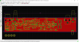
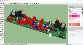
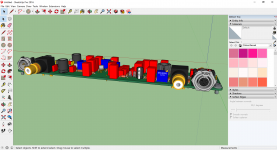
Caps (film pitch 5mm and width 7.2mm) are placed; PBA is for the moment 210x43mm, to stack for stereo and overall height <40mm (1U).
No 3D view today, sorry, missing license keys after W10 major update!
Good start in the coming week.
JP
Caps (film pitch 5mm and width 7.2mm) are placed; PBA is for the moment 210x43mm, to stack for stereo and overall height <40mm (1U).
No 3D view today, sorry, missing license keys after W10 major update!
Good start in the coming week.
JP
Attachments
I mean, to give me advise to finish the THAT output stage?
JP
What do you need? Their datasheet has the formula for gain resistors, both of the options have 6dB extra gain due to the outputs of the in-amps adding.
I will be off line from Mon - Thurs.
The THAT really is that easy.
Yes the THAT1512 was designed to make low noise audio preamps, I think it is the best choice here. Everything is on the same +-15V PSU.
Last edited:
OT, but has anyone noticed that "Silent Switcher" is a LT trademark ?
😱
😱
A warning, I wasted some time on this. Apparently those USB battery packs are mostly intended to charge cell phones and have a shutdown threshold. The Silent Switcher (and a low enough power circuit) does not have enough standby current draw to keep the battery on. This will frustrate you, not all of them do it (or the threshold varies). Luckily 40mA or so at +-15 translates to 240mA from the battery for me but only when fully populated. Cute fix below.
https://www.dorkbotpdx.org/blog/paul/battery_pack_load
Last edited:
my experience learns me that this packs are really noisy.
I'm finishing a 3S/6S LiPo pack design, no problem to adapt it
for 2x 7S!
JP
I'm finishing a 3S/6S LiPo pack design, no problem to adapt it
for 2x 7S!
JP
my experience learns me that this packs are really noisy.
I'm finishing a 3S/6S LiPo pack design, no problem to adapt it
for 2x 7S!
JP
The battery runs the switcher, no noise observed from supplies. Pictures were posted.
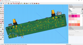
... ongoing, missing mica capacitors CD10 and CD15 3D models.
Layout optimisation today then PDF posting for control (before going SMD).
I´ve use a lot of USB battery pack but they sounds all bad in my ears, allways after strong filtering.
Mr. Wurcer do you have a sketch of the battery pack + silent switcher?
JP
Layout optimisation today then PDF posting for control (before going SMD).
I´ve use a lot of USB battery pack but they sounds all bad in my ears, allways after strong filtering.
Mr. Wurcer do you have a sketch of the battery pack + silent switcher?
JP
Attachments
- Home
- Source & Line
- Analogue Source
- A simplified universal differential or single ended phono preamp