input (female)/output (male) connectors?
G Type – Entertainment@Amphenol
http://www.amphenolaudio.com/wp-content/uploads/2015/07/AG3FCCH.pdf
http://www.amphenolaudio.com/wp-content/uploads/2015/07/55010613000111_ag3mcch.pdf
JP
G Type – Entertainment@Amphenol
http://www.amphenolaudio.com/wp-content/uploads/2015/07/AG3FCCH.pdf
http://www.amphenolaudio.com/wp-content/uploads/2015/07/55010613000111_ag3mcch.pdf
JP
Before folks run with something, I did some simulation and unfortunately the low transconductance JFET's do not work in the cascode stage. There is simply not enough degeneration offered by the 3k resistors. The RIAA conformance is degraded at low frequencies, it might not actually matter to some (~2.5dB @20Hz) and the simulator might be pessimistic. Patrick - I would check your versions for RIAA conformance I have not had a chance yet. This was actually my missing 0.2db in the plots I posted, since most applications will require some attenuation of low frequency artifacts I don't think this matters.
There are two options. The first is to go with the original circuit and use LSK389's or equivalent for the lower devices in the cascode stage and LS94 (apparently ungraded LSK74's which now seem to no longer be available) for the upper devices. This is OK any grade will do here, they need some matching but I think even 5% would be fine with the trim. I would go with the current source loaded follower output, where as stated there are several choices.
The second is to change the upper 3k load resistors to PNP current sources. I don't think this changes the spirit of the circuit. Then the LSJ689's are fine and currently available duals exist for all the sockets. Again I'd stick with the source followers, my original idea was to use the differential output with an external mic preamp such as exist on many external USB sound cards. They frequently have as low as 1K input impedance in differential mode.
There are other options involving higher supplies, etc. but I wanted to stay comfortably in the range of the Silent Switcher to stay on battery power.
I will try to illustrate some examples.
What´s the value and type for C3?
JP
Cartridge termination, it will depend on your cable and the specified loading. It all depends on how fussy you are.
I have done simulations using high hfe PNPs (BC327) instead of the 2SJ74, and they are OK on distortion.
But I shall use 2SJ74 anyhow.
I am using high Yfs FETs everywhere, so I am fine.
🙂
Patrick
But I shall use 2SJ74 anyhow.
I am using high Yfs FETs everywhere, so I am fine.
🙂
Patrick
I have done simulations using high hfe PNPs (BC327) instead of the 2SJ74, and they are OK on distortion.
Patrick
But then they're in the signal path, we do need to keep some ritual/religion after all. 😉 When I also made the common mode current sources simply NPN's and used the FET's as cascode I got an enormous effective impedance. Now the very low Cjs FET's work fine on both ends which is good for taking lots of gain out of the one stage with a high Z equalization network.
Thanks you Mr. Wurcer for the info about C3: are there some standard values, I´m thinking about 4p. DIL switch (good quality = TE) for paralleling of 4 different capacitors.
... and I like to modify design.
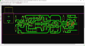
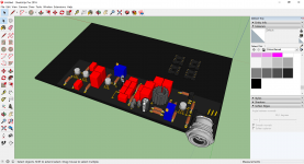
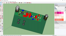
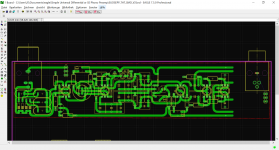
Here Sketchup view: mini-XLR, LSK489, LSK170, dual LSJ74, LSK389, LSK170, LSK489, LSJ689, THAT´s are waiting.
JP
... and I like to modify design.
Here Sketchup view: mini-XLR, LSK489, LSK170, dual LSJ74, LSK389, LSK170, LSK489, LSJ689, THAT´s are waiting.
JP
Attachments
> LS94 (apparently ungraded LSK74's which now seem to no longer be available) ...
Not only ungraded.
Also no noise spec. !!!!!!!!!!
Patrick
Not only ungraded.
Also no noise spec. !!!!!!!!!!
Patrick
>
Not only ungraded.
Also no noise spec. !!!!!!!!!!
The last date code looked decent for parameters, I can ask Paul Norton what the problem is. I was hoping it was just yield to grade, we have that problem where one customer wants lots of a premium grade and there end up 100's of thousands of extra low grade parts.
I will try to post the schematic with the current source load, it will work with just about anything, with infinite degeneration the noise and match almost don't matter. Are there any P channel Toshiba FET's still in production?
> Are there any P channel Toshiba FET's still in production?
No.
And when the sales deal of Toshiba semi finally goes through, I don't think there will be ANY Toshiba FETs of any kind anymore.
And that would certainly be within 2017.
I bought some 2SJ106s recently at sane prices.
But they are 10x noisier than 2SJ74s.
Patrick
No.
And when the sales deal of Toshiba semi finally goes through, I don't think there will be ANY Toshiba FETs of any kind anymore.
And that would certainly be within 2017.
I bought some 2SJ106s recently at sane prices.
But they are 10x noisier than 2SJ74s.
Patrick
buying last LSJ74 brocker stocks should be a fine investment? Group Buy?
The same story for NOS tube, Siemens KP capacitor, VFET, a long long list!
JP
The same story for NOS tube, Siemens KP capacitor, VFET, a long long list!
JP
Here's a rev of the circuit that I think makes sense in terms of utilizing avilable components without multiple ordering for matching. The input load is now a pair of pnp current sources with one of the LED's now an ordinary diode. It should be clear that a board could be laid out to trivially switch between the two versions with a couple of jumpers and part substitutions. I made R4 a pot which sets the common mode output voltage at the N and P nodes (this should have been there in the first place) this wants to be set close to 0 to maximize output swing. R8 trims output offset.
Attachments
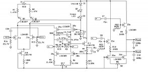

Here's a rev of the circuit that I think makes sense in terms of utilizing avilable components without multiple ordering for matching.
Isn`t R14 too high??
- Home
- Source & Line
- Analogue Source
- A simplified universal differential or single ended phono preamp