I already had one made.
But as usual I will not publish before finishing test build.
I made quite some changes to Scott's schematics, which he knew about.
The test build will take quite some more time as the JFETs need matching first.
So feel free to do an alternative.
Patrick
.
But as usual I will not publish before finishing test build.
I made quite some changes to Scott's schematics, which he knew about.
The test build will take quite some more time as the JFETs need matching first.
So feel free to do an alternative.
Patrick
.
Attachments

So the THAT's are out? Maybe it's a little low res, I can't really see where the styrenes go.
I'd be interested in running a GB for it.
I'd be interested in running a GB for it.
I am using WIMA FKP2. And no THAT needed.
Instead front end with 4x 2SK372GR.
I think one should use Scott design first to be safe.
I have no idea whether I might have a thermal drift problem without a differential servo.
And perhaps also a noise problem because of the high gain (aiming for 1000x at 1kHz)
Patrick
Instead front end with 4x 2SK372GR.
I think one should use Scott design first to be safe.
I have no idea whether I might have a thermal drift problem without a differential servo.
And perhaps also a noise problem because of the high gain (aiming for 1000x at 1kHz)
Patrick
So the THAT's are out? Maybe it's a little low res, I can't really see where the styrenes go.
I'd be interested in running a GB for it.
I'll put together a complete all on one sheet schematic, it will take a few days. I would not use my prototype board since it had a couple of errors where the lead spacings didn't match the components I got, and I used a less than optimal in-amp since I had them. Patrick is going for more gain up front (MC?) in either case a new board would be needed. I would lay a board out with provisions for both in-amps though they need not be both populated.
I also would suggest a set of component values that are readily available this might mean tweaking the values a little mainly in the RIAA network especially if you want +-.1dB out of the box. I was lucky the 3% caps I got were actually <1%. The values are small enough that there are several economical choices of high quality film caps.
I'm starting two big home renovation projects in the next month or so so I just can't commit any serious time to this right now.
The reason why I am using FKP2 is because of availability, in 1%.
And they are also available from Mouser, so everyone can get them.
Not everyone all over the world has access to special value and tolerance polystyrene caps.
But perhaps Scott has better sources. 🙂
Patrick
And they are also available from Mouser, so everyone can get them.
Not everyone all over the world has access to special value and tolerance polystyrene caps.
But perhaps Scott has better sources. 🙂
Patrick
But perhaps Scott has better sources. 🙂
No they were a surplus buy, no guarantee of availability but they have a lot.
https://www.surplussales.com/Capacitors/Poly-Unelco.html. You are better off with 1% up front, I was prepared to tweak values around and/or match.
Maybe if I do a GP I can include capacitors from the surplus place. Wimas are ok, but not really preferable.
A schematic and parts list would do the trick to get it all going with someone doing a layout. I'd rather try the THAT because it's different, and has some different qualities. It's not that Patrick can't make good stuff, its that I want to hear Scott W design, what you're hearing.
Also I wouldn't personally be using an MC, so I'd suggest either an optional schematic or leaving it out. Some people use step up transformers with them anyways.
> Wimas are ok, but not really preferable
Have you try A:B comparison to FKP2 (not just any WIMA) ?
(I also have many 1% Styrene's.)
Patrick
Have you try A:B comparison to FKP2 (not just any WIMA) ?
(I also have many 1% Styrene's.)
Patrick
I'm starting today with schematics according Mr. Wurcer posted schematics.
Saving time, Mr. Wurcer could then sketch modifications directly in schematics PDF.
I need to know JFET pairs LSK and LSJ.
SMD or THT design? I know, capacitors mostly THT.
I'm using EAGLE, Library Expert Pro fot packages, Ciiva for BOM and FreeCAD for 3D Cad and 3D PDF for PBA.
JP
Saving time, Mr. Wurcer could then sketch modifications directly in schematics PDF.
I need to know JFET pairs LSK and LSJ.
SMD or THT design? I know, capacitors mostly THT.
I'm using EAGLE, Library Expert Pro fot packages, Ciiva for BOM and FreeCAD for 3D Cad and 3D PDF for PBA.
JP
No I haven't done a direct A/B comparison. But I'm more interested in something besides a really old project I had, using styrenes, independent of this thread alone. They're just so small in value that it never really comes up.
THT please.
THT please.
LSK389 THT is almost double the price.
Trendsetter Electronics - Electronic Components Distributor
You can consider making an adaptor PCB to be 2SK389 pin compatible.
http://www.diyaudio.com/forums/group-buys/164785-lsk389c-soic-8-group-buy-3.html#post2236708
Then you will have plenty of choices, such as LSK389 SOIC, 2SK389, matched pair of 2SK170, 2SK372, 2SK369, .....
http://www.diyaudio.com/forums/solid-state/135154-next-best-thing-2sk389-2sj109.html
The latter two have higher capacitances but also higher Yfs AND lower noise.
IMHO worth having (at least the option to try).
http://www.diyaudio.com/forums/pass-labs/175040-more-fet-noise-measurements-euvl.html
Patrick
I only use Toshiba's.
But that is just me, so I do my own boards to exactly suit my needs.
🙂
Patrick
But that is just me, so I do my own boards to exactly suit my needs.
🙂
Patrick
No I haven't done a direct A/B comparison.
FYI the RIAA caps are 2 - 9.375nF and a 12nF || 1.7nF the output coupling cap is non critical in value I used 75nF. the 23265 Ohm resistor is two resistors in series, I just used one of the javascript calculators that generates all possible choices and picked one I had. Everything else is standard 1%. The RIAA plots I posted were done with no adjustments or trims.
If you don't use differential in you will want the option to put the termination on one side and ground the other. I never determined absolute polarity you may want to make sure it is preserved through the signal path and label accordingly
You may want to consider simple current source biased source followers on the output. I designed this to drive up to 2K load, the in-amps are no load at all. This would simplify the build considerably. I think Patrick would agree there should be no sonic consequences. I'd try the classic 2 FET zero offset follower trick. Just to mention, one might think you could go right into the in-amps but their current noise is a problem at this impedance level.
The circuit should work fine with some of the new LSK P and N FET's in place of the Toshiba's but I would hope someone would verify a prototype or at least a sim. I would trust Bob Cordell's models since he is working with Linear Systems on applications.
Last edited:
The output source followers can be anything if you only want to drive 10k load or so.
I am planning to use 2SK369BL because I have lots. And they will drive 2k will ease.
But for 10k, they can be LSK389, 2SK170BL, 2SK117BL, 2SK209BL, .....
Even BF862 if you cascode them (because of limited Vds).
I have running Spice files of my own version and also Scott's original version.
But if Scott would post an updated schematics, I shall supply a Spice file accordingly.
(Excluding the THAT.)
Patrick
Last edited:
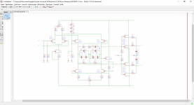
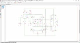
SMD and THT Version.
Need help for choosing C3, C1, C5. C7 and C8 aren´t anymore critical (other value possible?).
The RIAA capacitors coming from WIMA, FKP2 1% Series.
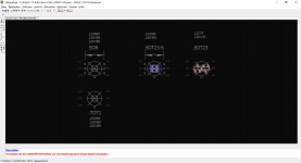
I´m working on an universal JFET Adapter (TO92, SOT23, SOT23-6, SO8 TO71, black foto), as I´ve done for Ale´s CCS.
Schematics PDF available after coming commented corrections (THAT part missing).
JP
Need help for choosing C3, C1, C5. C7 and C8 aren´t anymore critical (other value possible?).
The RIAA capacitors coming from WIMA, FKP2 1% Series.
I´m working on an universal JFET Adapter (TO92, SOT23, SOT23-6, SO8 TO71, black foto), as I´ve done for Ale´s CCS.
Schematics PDF available after coming commented corrections (THAT part missing).
JP
Attachments
Schematics PDF available after coming commented corrections (THAT part missing).
JP
The schematics are too fuzzy in the text to help.
I have running Spice files of my own version and also Scott's original version.
But if Scott would post an updated schematics, I shall supply a Spice file accordingly.
(Excluding the THAT.)
The THAT in-amp output doesn't really need simulation, it's simply a gain block.
I'm working on it, the LS models situation is sort of a mess at times. I noticed Bob does not have models for the LSJ689 PFET, I'm going to try and run a sim using the model parameters they have on their site. I have plenty of samples but am not setup right now to extract/verify parameters, the DC ones are all we really need.
Last edited:
- Home
- Source & Line
- Analogue Source
- A simplified universal differential or single ended phono preamp