stereo...
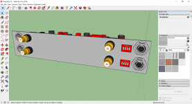
Working on PDF documentation, BOM included.
JP
Working on PDF documentation, BOM included.
JP
Attachments
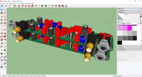
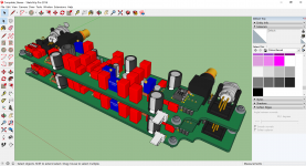
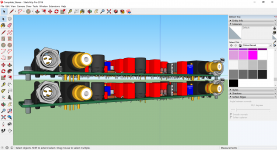


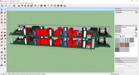
there is no access to dip switches on the bottom board, you may consider piano dip switches with access through the panel cutout
Nice work JP.
Hate to add more but the trimmers maybe be accessible when stacked as well, ala side screw, with the right orientation.
Hate to add more but the trimmers maybe be accessible when stacked as well, ala side screw, with the right orientation.


Documentation, someone to check? Modification, improvements?
On the NIN input, have one 47k5 permanently to gnd, and another 47k5 optionally
strapped in parallel with it to gnd. This way the NIN input will never be unterminated
if the shunt is removed or forgotten.
Last edited:
Hi,
the ´error´ in the input configuration of the load resistors has been mentioned before.
Connect both 23k7 in series between PIN and NIN.
Now connect Pin2 of the 3-pole jumper to AGND.
Connect Pin1 of the jumper to NIN and Pin3 to the midpoint of the 23k7 resistors.
Position 1-2 is unbalanced input, 2-3 balanced input mode.
The JFET V103 is not a very good current source.
You may use a different JFET instead (4391 or 4392, depending on available voltage, in conjunction with higher source-R) or cascode the SK170 with an 4391 or 4392.
You could also beef-up the output stage, especially if You could expect to connect source loads lower than say 10k.
Besides, running the JFETs hot, i.e under high ID and high Vds conditions, combined with a high valued gate resistor, increases the risk of lethal latch-up considerably.
I´d recommend to add bipolar booster transistors in a CFP configuration, which not only allows to run the JFETs on lower power and to drive lower impedance loads but also adds sonic slam to the allsooften rather filigrane sounding JFET buffers.
jauu
Calvin
Last edited:
The JFET V103 is not a very good current source.
You may use a different JFET instead (4391 or 4392, depending on available voltage, in conjunction with higher source-R) or cascode the SK170 with an 4391 or 4392.
You could also beef-up the output stage, especially if You could expect to connect source loads lower than say 10k.
Simplicity was the original point. The CMRR is very high without any change, the inevitable slight mismatch in cable capacitance will dominate. I'm not sure if you're referring to actual measurements or not. In any case a harmless change.
I have to repeat the warning as shown there needs to be a buffer/gain stage. I recommended a low noise mic preamp like the THAT 1512 preferably two of them to configure diff/single ended out. The buffers drive no load in this case. The gain here is too low to use with a conventional line stage.
EDIT - "sonic slam to the all so often rather filigrane sounding JFET buffers." - I guess you're not talking measurements. Since virtually every Schoeps microphone (and many others use an open-loop JFET phase splitter running at 1mA or so I think we're in good company.
Last edited:
Documentation, someone to check? Modification, improvements?
JP
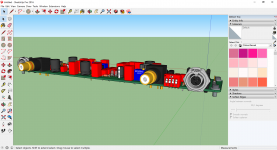
Beautiful art JP. What cad program did you use to draw this schematic ?
Scott, Calvin, 1512 is on the page 2 of pdf
Thanks Dimitri, missed that. Trying to keep things simple but not to simple.
I´m using Eagle since ten years and owned a big library (THT, SMD or specials as tube). I´m using it successfully for all kind of electronic development.
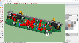
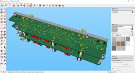
Coupled with Library Expert Pro for packages, FreeCAD, Blender and Sketchup for 3D modelling (STL modelling).
Starting with FreeCAD PCB last week to enable Eagle board import and STEP 3D model mapping for mechanical integration of electronic boards
Very busy this weekend, don´t know if I´ve time for the mods...
JP
- Home
- Source & Line
- Analogue Source
- A simplified universal differential or single ended phono preamp