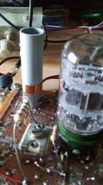
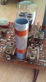
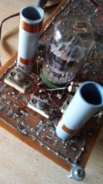
This is the first attempt to make the IF strip. The tube is a dual pentode 6AR11 remote cutoff biased with 82ohm ad 10nf in cathode and about 140VDC at plate and screen. Independent pin for suppressor is grounded. The coil is about 6ųH tuned with about 30pF. 20T copper wire 0.3mm. Former is 15mm diameter. Anode load temporarily is a choke.
Attachments
60 years ago my father bought a philips FM tuner kit. After assembly he sent the unit in for tuning of the MF stages and ganging of the permeability tuning. it had an E80CC tube as far I remember, I was only 6 yrs old at the time.Here more pics showing the oscillator beating with the sweep generator signal to check tje cleaness of the signal generated, and a more expanded pic of the layout. The coil still unused will be the RF amplifier anode load.
E88CC rather than E80CC, I suppose. The latter one wasn't exactly designed for FM frequencies.
Best regards!
Best regards!
A question for those with experience. My actual idea is to use those dual pentodes cascaded (not cascoded) with AVC. Now I may add a third stage with the high gain pentode inside 6BW11 (there are available a couple sharp cutoff pentodes, one with gm~8mS and another with gm~11mS.) without AVC. It is suggested in the patent from Seeley that there is no need for limiter previous to the detector but a good AVC in order to keep the voltage in the storage cap stable. Now, which may be the advantage of a third stage?.
Note that as I progress, my concept of the rig has been changing, of course.
I saw circuits like Fisher 1000 with 6 (six) stages but with lower gm tubes.
Note that as I progress, my concept of the rig has been changing, of course.
I saw circuits like Fisher 1000 with 6 (six) stages but with lower gm tubes.
Attachments
My experience with tubes and 10.7 MHz IF led to abandoning that topology. Using 3 stages with EF184, Philips IF transformers (bandpass), oscillation was difficult to eliminate: even filaments had to be decoupled and fed via chokes. So gain had to be reduced to the extent that the last stage only worked as limiter. That had its own set of problems, one of them the issue that asymmetric limiters transform AM to PM. Hence my 1976 receiver used 2nd conversion to 1.7 MHz with cheap 27 MHz quartz at fundamental frequency. The 2nd mixer, high level single balanced with 2 X 3N211 hence the piece of copper for cooling, with holes containing them. PLL below the IF section to shield VCO from IF input. Limiters with the well known uA703, after the (not so simple) filter (which had to be calculated manually, back then). This concept worked and works very well, and could deal with 300mV signal from the local transmitter in the Netherlands. With tubes I would use something similar, no matter the amount and or space required.
Attachments
Ok. Thanks all suggestions. This week I'll try the first coupling. Not sure if overcouped or damped Q for bandpass stage. But sure with "vacuum tubes state". No ss here.
Difficulties found to get the proper separation between coils for adequate k between them.
Difficulties found to get the proper separation between coils for adequate k between them.
Don't forget the issue of Vg dependent Cgk: TV IF often used pentodes with non-decoupled cathode resistor to decrease the effect of detuning filters due to AGC. For 10.7 MHz FM IF the easier solution is to design IF filters with low L/C quotient and tubes with low Cgk, requiring more (but less critical) stages.
Good point! This argument has led to the development of the EAF801 out of the EBF89. An undecoupled cathode resistor yields to more bandwith and better stability in FM stereo IF strips. The simple difference between both tubes is that in the EAF801 one of both diodes isn't connected. It's pin connects to the internal shield, which in the EBF89 shares the cathode/suppressor grid pin.
Best regards!
Best regards!
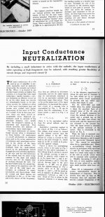
I found in an old WW magazine a recipe that using a small inductor in the cathode may cancel out input conductance with lower gain loss than using unbypassed cathode resistor. Also it seems that H. A. Wheeler has published a paper where he suggest to use a small inductance in the screen supply, a solution widely used in the 6CG8 and derived tuners. But could't find such a paper to learn the appropiate value of such inductor.
Neither I could found a good formulae to find the wright separation between single layer coils for a given k or M. Only an approximate one using old imperial units that introduce further errors.
Neither I could found a good formulae to find the wright separation between single layer coils for a given k or M. Only an approximate one using old imperial units that introduce further errors.
Last edited:
For Kaypirinha:
Unfortunatelly I haven't such a tubes, and actually in my country it is imposible to get them. I am crazy for get some cheap and interesting tubes, 6AC9 for example, that has a large gm pentode plus a 6AL5 in the same envelope, but I could't find it here. And the currecy between U$S dollars and AR$ make it actually prohibitibe.
Unfortunatelly I haven't such a tubes, and actually in my country it is imposible to get them. I am crazy for get some cheap and interesting tubes, 6AC9 for example, that has a large gm pentode plus a 6AL5 in the same envelope, but I could't find it here. And the currecy between U$S dollars and AR$ make it actually prohibitibe.

Osvaldo, you're fine with what you have. My posting referring to EAF801 and EBF89 was meant as an example to verify what has been written before by Aridace, concerning unbypassed cathode resistors in FM IF strips. I've read it in an article from about 1964 in the then well renowned German tech magazine FUNKSCHAU.
Btw, EF89 is the same pentode...
Best regards!
Btw, EF89 is the same pentode...
Best regards!

Why did you pick 12mhz, 20mhz would move all oscillators past the FM band.
Eg tuning 92.1 has a local osc at 102.8 mhz to generate the 10.7 mhz IF
Eg tuning 92.1 has a local osc at 102.8 mhz to generate the 10.7 mhz IF
Back then, I occasionally read magazines so discovered the effect in my DIY FM radios. Some have golden ears, others have golden touch so "feel" a tuning asymmetry via the magic eye display. It was rather pronounced, disabling reception on adjacent channels of the national (strong) transmissions. It added to the notion "need 2nd conversion with IF low enough to avoid such effects". BTW those remote cut-off pentodes might be rather useful in a balanced peak limiter, as alternative for soft clipper.Good point! This argument has led to the development of the EAF801 out of the EBF89. An undecoupled cathode resistor yields to more bandwith and better stability in FM stereo IF strips. The simple difference between both tubes is that in the EAF801 one of both diodes isn't connected. It's pin connects to the internal shield, which in the EBF89 shares the cathode/suppressor grid pin.
Best regards!
Ok. 20MHz for IF sounds too high for me.
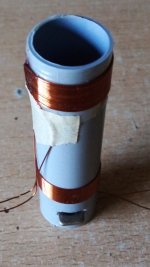
In the other hand I made the first IF transformer air cored. Below is the pic. The upper winding is movable sliding in the bobbin as the wire is wound on a short piece of unglued mylar tape. This is the grid secondary. The lower one is the plate coil and is fixed. The piece of light brown tape is temporarily there to fix the coil while the cyanoacrylate adhesive fix the coil to the mylar tape, so it doesn't unwind while adjusting coupling. Tomorrow I will wire it to the protoboard and shall see what happens and if it behavior is proper one.
Respect to EF89 and EBF89 I have few of them and by this moment I reserve them for the AM tuner Project already posted in this forum some years ago.
Second conversion is very common in ham rigs as the chanels are 5KHz only, using 10.7MHz and 455/465KHz in the second IF, but never I saw a comercial rig using double conversion for broadcasting receivers.
Attachments
The panasonic STG7 has a tripler to 32.1Mhz at the end of the IF, creating a triple deviation, and then subtrackting LO of 31.3Mhz such that a 0-800Khz swing signal results for an ultra linear counting detector. the receiver has the lowest distortion reported for any FM receiver (0.01% in mono). it´s one of a kind
Ok. But such a thing is too complex for me. I'm a humble ham radio and I have few old instruments already commented here. Also this is my first experience in the topic.
I don't say that there isn't such a multiple conversion devices,I said that I didn't saw them, and, again, it would demand lots of stuff difficult to find or unavailable here thanks to our ******* politics and their ******* actions.
I don't say that there isn't such a multiple conversion devices,I said that I didn't saw them, and, again, it would demand lots of stuff difficult to find or unavailable here thanks to our ******* politics and their ******* actions.
More than 60 years ago I didn't have any instrument, not even a volt meter. So radios were constructed "end to start". When the AF amp worked, the 2nd IF was built, and tested "by ear" with improvised mixer and oscillator. When that worked, the proper mixer and (fixed frequency) LO were added. Unless an error had been made, it worked as expected and the front end was built. With FM that procedure wasn't different as long as there were sufficiently strong transmissions.
The advantages of low (2nd) IF are many. Q factor of LC less important, IF gain can be much higher without instability, S/N and linearity can be better than obtainable with high IF. For just local reception, image rejection isn't a problem and the IF can be low. A good example of that is the Philips TDA7000 - which I also used as 2nd IF + demodulator in a (published) design for a wireless mike.
The advantages of low (2nd) IF are many. Q factor of LC less important, IF gain can be much higher without instability, S/N and linearity can be better than obtainable with high IF. For just local reception, image rejection isn't a problem and the IF can be low. A good example of that is the Philips TDA7000 - which I also used as 2nd IF + demodulator in a (published) design for a wireless mike.
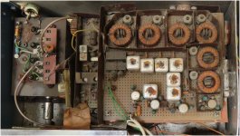
I had to reorder and neutralize adding a smaller mica trimmer the first stage of the IF amp as it was very unstable. 6AR11 has a gm~11mS and lots of gain. Now I shall make the second stage.
Attachments

- Home
- Source & Line
- Analogue Source
- A new FM tuner with Compactron Tubes