I'm familiar with "Medicos de pueblos fumigados" in Argentina and similar regional issues (did a lot of homework before emigrating to Panama).
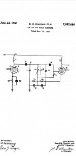
It's technically correct that a tube limiter stage ends up as working in class C, because limiting regards overdriving an amplifier in a way that increases the negative voltage of the control grid. It's precisely what should be prevented for a good limiter. Limiting should happen to current and that requires long tailed pair / differential amp, whatever the active device. If that is impossible, consider the use of a buffer followed by symmetrical diode clipper and in a way that none of the IF amps changes operating point at strong signals. Another reason for that is maintaining IF selectivity: the change to class C when limiting affects Cin and loading so detunes the IF.
It's technically correct that a tube limiter stage ends up as working in class C, because limiting regards overdriving an amplifier in a way that increases the negative voltage of the control grid. It's precisely what should be prevented for a good limiter. Limiting should happen to current and that requires long tailed pair / differential amp, whatever the active device. If that is impossible, consider the use of a buffer followed by symmetrical diode clipper and in a way that none of the IF amps changes operating point at strong signals. Another reason for that is maintaining IF selectivity: the change to class C when limiting affects Cin and loading so detunes the IF.
It is said that low screen voltage is needed to secure saturation of plate current and safe operation under no singnal condition and no grid leak bias.
Correct, and for another reason, see below.
Because of the above, and because you want it to clip positive symmetrically wth the grid leaking limiting in the negative direction, not many volts above that absolute voltage. In any case there is plenty of signal. The two tuners I deal with most both deliver several volts to the detector.But why is needed a low plate voltage too if pentode current is cuasi independent of voltage at anode and with normal anode voltage, more signal can reach detector stage?
Ok guys, I understood. I saw some patent of the tube apogee with a similar configuration to the above posted by Aridace from the Elektor magazine but with tubes and another in which diodes are biased using the voltage drop across a non AVC stage cathode bias network. But ot is too early to fix this item as I am currently thinking in the design of the IFT's.
Attachments
The LC-series discriminator produces little distortion, and the major contribution is 2nd harmonic. Ran a simulation at 10.7 meg (pics). R1 limits the current (12 mA) and lowers Q. The FFT's regard 75 and 150k deviation (10k modulation)


Yeah. The circuit I depicted partially comes from a 3N128 MOSFET and a voltage divisor with 5nF caps @ 67KHz as it was a SCA recover some time in use at home.
Output in the circuit I simmed is rather low but no issue for a low noise tube. As you're constructing well screened IF transformers, the series LC won't be an issue either. Simming tubes above ~10 MHz is a nonissue because at least for Microcap, in the models tube input impedance is ignored.
Bad enough not to use tube sims except for (some) audio. But I'm used to that, as Microcap's dual gate mosfet models ignore G2 linearity and manufacturer's data has to be used for calculation / estimation of linearity. But that has become difficult too as data on devices deemed obsolete has been curbed to the minimum required for "replace & repair".
MOSFET distortion is notoriously difficult to model anyway (though not impossible with modern MOSFET models). But that's off topic.
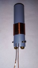
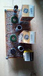
Just minutes ago I asked the greengrocer for the short plastic tubes they discard to thrash, from the paper rolls for electronic cash registers. They are very interesting for hand winding the IF traffos. Doing the maths for coils of same diameter as winding lenght.
Let's see what happen.
Let's see what happen.
Attachments

An alternative would be to use one tube for 2 separate coils, one of which can be rotated to adjust coupling. That way your receiver can have adjustable bandwidth at little extra cost.
My idea is to make the anode coil fixed, and the next grid one, as suggested by Langford Smith, say using glued tape with the adhesive side outwards and wind the coil over it. Thus, this secondary coil may be moved easily to and from the primary to adjust k and M as Q is unknown for me.
Some months ago I made a xtal controlled pseudoFM modulating the crystal with several ECL84's and a pair of EL84's giving 4W @240VDC and 50ohm load. The coupling between tripler stages was magnetic but coils had their axes parallel wound on different bobbins. It gave me good results, so I don't discard try this mechanism again.
Some months ago I made a xtal controlled pseudoFM modulating the crystal with several ECL84's and a pair of EL84's giving 4W @240VDC and 50ohm load. The coupling between tripler stages was magnetic but coils had their axes parallel wound on different bobbins. It gave me good results, so I don't discard try this mechanism again.
Attachments


Variable IF BW doesn't have to be complicated. The implementation near the bottom of the page is possible for FM as well.
Continuously variable IF
Continuously variable IF
This one? But as the coupling is altered, you modify also M and both tuned circuits modify their resonant frquency. So you need to change the oscillator frequecy to move the IF central frquency or all trimmers in such IFT's. Else the reception will be detuned, imo.
Attachments
The example uses capacitors to adjust the proper IF (no ferrite or other core) so there's no other influence than changing the coupling. But the effect from changing the distance between cores could be made negligible for LC with high enough Q. A simpler DIY solution with few moving parts is to rotate a coil perpendicular to its axis and then the distance remains about the same. Rotation then is less than 90 degrees, limits are set for maximum and minimum coupling.
Ok. Thanks for all suggestions. I am now thinking in change a bit the project using a compactron with double pentode gm ~11mS. I got more plastic tubes and literatures for the calculus and design of the IFT's.
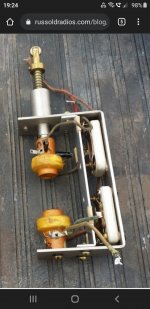
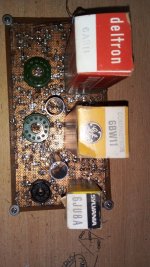
This is the new mixer's plate tunning coil #12MHz // with 30pf silver mica. It supersedes the depicted previously on brown plastic tube. Any similitude with vintage radios short wave coils is NOT a coincidence.
Attachments

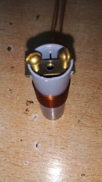
In this case, no one. This will be a single coil pi coupling to first IF stage through a short piece of coaxial line (say, 10cm).
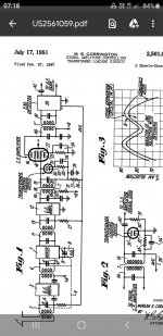
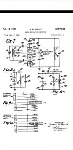
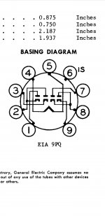
For the remaining of the IF I believe that an overcoupled transformer (double hump) and perhaps a critical or transitional stage. But still I am in doubt with the number of stages. I saw schematics in the web with as little as two tubes to other with too much as six. Also in doubt is the tubes to use. Original idea was two stages with EF184 but now I'm thinking in two halves of 6BN11 plus a third of 6BW11. And saw an interesting version of the ratio detector in the original Seeley patent using full wave detector in place of half wave. Ideal to the 6JU8A quad diode. I have several of them.
For the remaining of the IF I believe that an overcoupled transformer (double hump) and perhaps a critical or transitional stage. But still I am in doubt with the number of stages. I saw schematics in the web with as little as two tubes to other with too much as six. Also in doubt is the tubes to use. Original idea was two stages with EF184 but now I'm thinking in two halves of 6BN11 plus a third of 6BW11. And saw an interesting version of the ratio detector in the original Seeley patent using full wave detector in place of half wave. Ideal to the 6JU8A quad diode. I have several of them.
Attachments
- Home
- Source & Line
- Analogue Source
- A new FM tuner with Compactron Tubes