I found those intetesting means for neutralizing the IF amplifier without several components added. The sources are self explanatory: an US patent and an article from IRE Proceedings from 1943 free available in the web.
Very stormy today here.
Very stormy today here.
Attachments

I made a mistake when calculation of the number of turns of the coils for IFT's, by subestimating stray capacitances, and then it was impossible to tune the stage, the resonance peak was about 9MHz in place of 12. So I rewound all coils and now it is very clear the peak. I now am using 16 turns 0.4mm copper wire over 15mm cylinder occuping 7mm long (close turns).
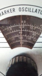
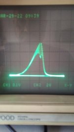
There are two sweep of the stage, one with large deviation and the other with narrow sweep, also showing the 12MHz marker at both
There are two sweep of the stage, one with large deviation and the other with narrow sweep, also showing the 12MHz marker at both
Attachments

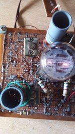
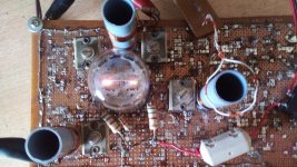
Today I completed the second stage using the second unit at 6AR11 compactron. The amplifier is still unadjusted in which coupling coefficient k regards, but it is at resonance, and the effects of limiting at the second grid is vissible, although it is cathode biased and remote cutoff units are used. Thus, a hard clamping limiter will be used of the kind already illustrated.
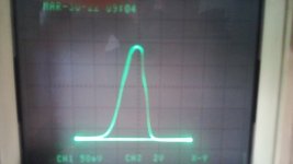
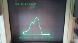
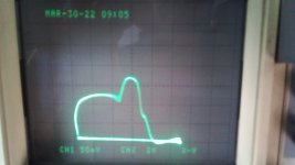
Following, it is depicted the actual physical arragement and 4 oscillograms using the sweep oscillator Eico 368 and analog CRT oscillo. In the first the signal is well below the clipping level, and the remaining with increasing levels up to 0.5V rectified at the grid leak plus 1.8V cathode bias. The marker 12MHz as is amplitude modulated over the signal, clearly dissapears as limiting action take action, although its level remains unchanged through the test.
The ring about the third coil white and orange is a capture single turn coupled to a germanium diode and crc low pass filter with two 100pF and 10Kohm to detect the signal.
Attachments

Last edited:
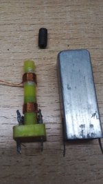
New permeability tuned IF transformers. The bottom coil is the primary and is fixed in place. Top one is the secondary and is moovable in order to adjust M and k for proper BW. Tunning capacitor is 22pF @ 500V silver mica. The plate cap isn't directly in parallel to the coil, it returns to ground using a dedicated pin.
The screen decoupling cap is only 910pF mica plata. This make the screen alive for RF of about 2.7VAC and is out of phase respect to the plate signal, neutralizing the coupling trough anode-grid capacitance. It is fully stable irrespective the high gm of the tube. Anode and screen voltages are about 140VDC.
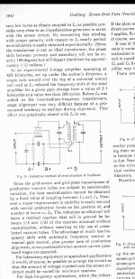
This idea isn't mine and I learned it reading the article "Neutralization of Screen-Grid Tubes to Improve Stability of Intermediate-Frequency Amplifiers" by C. A. Hultberg in the Proceedings of the IRE December 1943 available free in the web (worldradiohistory.com).
The screen decoupling cap is only 910pF mica plata. This make the screen alive for RF of about 2.7VAC and is out of phase respect to the plate signal, neutralizing the coupling trough anode-grid capacitance. It is fully stable irrespective the high gm of the tube. Anode and screen voltages are about 140VDC.
This idea isn't mine and I learned it reading the article "Neutralization of Screen-Grid Tubes to Improve Stability of Intermediate-Frequency Amplifiers" by C. A. Hultberg in the Proceedings of the IRE December 1943 available free in the web (worldradiohistory.com).
Attachments


Quite an improvement on the previous IFT's, and the real art of DIY!
I would wanna bigger cans. They are 18mm side, but is what I could find. The slugs are old and crack easily.
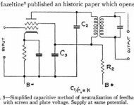
This is my schematic extracted from the source already mentioned.
As can be seen, the tuning capacitor returns to ground in place of doing it to screen. Thus RF resonant current flows trough bypass capacitor appearing an out of phase signal at screen grid whose voltage is proportional to both capacitors in series and counteracts plate-grid feedback. This is the core of the neutralization means and really does it job pretty fine, much better I thought.
Certainly, the non-bypass condenser was increased from 910pF to 1500pF silver mica and it is still stable.
Attachments
. . . . . . Over the copper tubing, a thin layer of electroltic copper was deposited using copper sulphate and an electrolytic solution, for reduce the superficial resistance and increase the Q of the tunning device, in fact oscillator's grid bias decrease less than a volt from one end to other of the oscillating range.
. . . . . . . .
If the difference between treated and untreated is important to the intended function of the circuit, does oxidation over time become an issue?
Thanks
Larger screens for the IFT's would increase Q but the BPF then would need lower load resistors to maintain the same passband. Unless the cores have much loss, I think the Q will be at least 100.
Interesting way of neutralization. An alternative would be to lower the impedance at the plate enough, by using a tap on the IFT.
Interesting way of neutralization. An alternative would be to lower the impedance at the plate enough, by using a tap on the IFT.
But this mean doesn't need to reduce the loading on the tube taking advantage of full stage gain.
The advantage of larger cans is for my eyes mainly. Too small things are actually more difficult to see too.
5 or 6mm slugs were more common and had saved several of them.
Respect to oxidation, copper once oxidized, doesn't continue doing it. It creates a protective layer like aluminum, etc., that protect itself from future oxidation else in presence of sulphur. Not my case. See lots of copper pieces in perfect state from myriads of centuries ago.
For full stage gain the inductors would have to be tuned with the tube caps Ca(k,g2) and Cg(k,g2) only. Local stations can cause the 1st IF stage to start limiting. With a grid leak R, Vg will change and with that, Cg(k) which causes detuning. That can be limited by a non-decoupled cathode resistor (usually 22...47R) which also decreases gain. Absence of a grid leak R can cause the IF stage to saturate which negatively affects the plate BPF. Hence DIY design where lowest possible cost is a nonissue can apply more IF stages with lower gain per stage but without detuning BPF when changing / aging tubes or due to limiting.
For really small things I use a loupe but it's rarely needed: it's enough to do anything at close distance without the glasses needed outside. It's the major advantage of myopia, also a big + for reading (food and other) labels.
I still have a few Toko VHF coils with Al slugs. For the brittle ferrite slugs you need to adjust position with a tool made of soft plastic, softer than provided in most kits, so DIY.
Interesting point. I still am unsure if use AGC or not. Thinking to use a first stage AGC controlled followed by a second with a limiter outside the amplifier itself. Using one double diode inside 6JU8A. Schematics already depicted here in the US patents above included in the thread.
I learned that when a tube is neutralized, the effect of grid capacitance is cancelled. But not sure if this is true, then the detuning efect by varying the grid bias and as a consequence, tube gain, the detuning effect is also vanished.
I learned that when a tube is neutralized, the effect of grid capacitance is cancelled. But not sure if this is true, then the detuning efect by varying the grid bias and as a consequence, tube gain, the detuning effect is also vanished.
Last edited:
When you use neutrodynization to eliminate Miller effect and the negative conductance it can cause when the gain drops with frequency, you still have the grid-to-cathode capacitance and all the other capacitances in the circuit. They just don't get aggravated or converted to frequency-dependent negative resistors by Miller effect anymore.
Ignition pulse noise disappeared once cables with built-in resistance were introduced (now standard). That allows the use of AGC w/o problems. A symmetric limiter is preferable and with diodes it's possible to prevent all aforementioned issues resulting from changing operating point.
Been playing around with an old Clairtone console. Fm is good but output level varies with signal strength. The most interesting thing is the 2 tube AM reciever is outstanding going to about 9khz (audio) while maintaining channel selectivity. Much better sounding then transistor or IC am radios.
In the Americas, local AM radio (I think <5KW) can use 10 KHz as upper audio modulation frequency. Higher power, just 5 KHz. All modern (and insensitive) BJT RX are using filters for those higher power transmissions (so apart from detector and audio distortion, sound awful). One of the best AM radios ever made is Best AM radio yet and it certainly would be possible to design a very high performance FM radio with tubes as well. Sellers of special and / or vintage parts might start a competition to improve sales...
Modern AM radios typically have a small audio bandwidth to on paper improve sensitivity. The smaller the bandwidth, the less signal you need to get 26 dB audio signal-to-noise ratio.
Several times, awfull AM listening is because of improper receiver design. I could take advantage of good AM reception in my High Audio Quality AM Tuner published here, by means of a novel demodulation mechanism using a LCL T Network filter following a cathode follower which vanishes loading of the detector diode itself, and also having a much better filtering characteristic than normal passive CRC filtering. It interesting how much improved audio is recovered in this way.
I learned that capacitive loading of the detector diode is imperative in order to get rid of RF carrier; but also causes distortion of the signals with fast negative slope and higly modulated signals as I pubished there and demostrated mathematically by F. E. Terman in his books. My filter, in the other hand, resembles more to a choke input filter, but at such frequencies and impedances, a good RF choke is difficult to get at hand. Interposing a cathode follower matching the LCL T network avoids both inconveniences at the same time.
I learned that capacitive loading of the detector diode is imperative in order to get rid of RF carrier; but also causes distortion of the signals with fast negative slope and higly modulated signals as I pubished there and demostrated mathematically by F. E. Terman in his books. My filter, in the other hand, resembles more to a choke input filter, but at such frequencies and impedances, a good RF choke is difficult to get at hand. Interposing a cathode follower matching the LCL T network avoids both inconveniences at the same time.
- Home
- Source & Line
- Analogue Source
- A new FM tuner with Compactron Tubes