During the early 1960s I built a small 1V1 with an ECH81 and an EL84. It showed the interesting effect that with the proper level for the regenerative grid leak detector, it provided great audio quality, functioning as product detector instead. Unless (selective) fading caused the carrier to fall below the level required for synchronization, sound quality remained very good. Nowadays such a tube receiver could be built using a PLL with current controlled oscillator: 1 6JH8 (or 7360) for the PLL + CCO and another one as product detector.

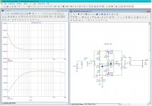
This is the schematic of the IF stage as it is until this moment. Tube is a double remote cutoff pentode 6AR11 but it may change. Note the similitude with the schematic proposed by Hultberg. This isn't casual :=)
Grid leak resistor isn't necessary, but it is there to measure the point in which the tube starts to drive grid current or is driving positive, that's the same. If the stage runs properly, the bottom of it will be removed from ground and receive the AGC bias if any. Otherwise it will be erased together with the decoupling capacitor.
The grid inductor very possibly, will be a π tank or a link coupling from the front end. At this moment, it is a link with 2 turns over the main tuned inductor, consisting in 24turns 0.22mm varnish copper wire, used also in transformers and motors. It has been wound in two layers of 12T each, using cyanocrilate to fix the first layer to bobbin, when dryed, the second layer over it and again fixed same way. Plate winding is exactly the same as it. The still unused secondary, is done equally but not fixed to bobbin, it is fixed to a short piece of thin mylar paper in order that it may slide to or from the primary to adjust coupling.
Attachments
Yesterday I tryed a 6BN11 which contains two 13mS pentodes (in fact beam tetrodes) in the same envelope but become extremelly unstable, being impossible to neutralize it and stop oscillating. I don't understand why, because geometry inside the tubeis very similar. Thus I returned to the 6AR11 again.
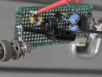
These actions requiered complete dissasemble of the protoboard as base pining of both are incompatible. Also I rewired it in a more tidy way.
These actions requiered complete dissasemble of the protoboard as base pining of both are incompatible. Also I rewired it in a more tidy way.
With 2 pentodes so physically close, Cg1-a2 or depending on configuration, Cg2-a1 (increased by tube socket) could cause instability because "between" those caps are 2 stages of maximum amplification. Before building, measuring components (expected Q, value of socket + wiring caps) and simulating that could give a clue about stability.
But in the attempt to replace the pretty bottle, the second unit was unwired. Some time after, I wondered if I over-neutralized the 6BN11. Over neutralization may also configure an oscillator if too much signal passes through neutralizing mechanism.
In my case, and referring to the Hultberg's system, I found that I need a larger cuasi-decoupling cap than the value obtained from the formula published by the boy. Perhaps 6BN11 needed still a larger sized condenser. By this moment I shall continue with 6AR11.
In my case, and referring to the Hultberg's system, I found that I need a larger cuasi-decoupling cap than the value obtained from the formula published by the boy. Perhaps 6BN11 needed still a larger sized condenser. By this moment I shall continue with 6AR11.
Long ago when confronted with an oscillating RF or IF amplifier, a simple test was to reduce gain by loading grid and / or anode LC. If oscillation continued it was rather likely the stage was oscillating at VHF (parasitics, few hobbyists had a scope to see that) and insertion (grid and / or anode) of a small resistor usually fixed that. But in most cases the oscillation stopped when gain was lowered enough. Then the work with screening, positioning differently and more / better decoupling started. With 3 IF stages I even had to decouple each heater.
Thanks for this datum. Respect to oscillation, in my case usualy seems to be of the tuned-plate tuned-grid because it changes frequency with adjusting slugs and eventually it dissapears.
Hooking the tip of the scope at the screen of the pentode (lower impedance and high "cuasi-decoupling" cap) reveals oscillations whose f is close to the IF value, say 11~13 MHz. Remember again my IF value is 12MHz not the standard of 10.7.
During free time this week I shall continue doing some testings.
Thanks for your suggestions and help.
Tptg is the most common cause for IF stage oscillation indeed. But I also encountered tp(2)tg(1) (or worse, tp(3)tg(1)) oscillation and that was where the decoupling / screening circus started. My favorites were EF183 / 184 (high gain, low noise). Back then, nobody thought of using an ECC88 or equivalent as less oscillation-prone cascode IF amp. But nowadays such dual VHF triodes are fairly cheap so I wouldn't use anything else and would build an "all triode" FM RX. Another advantage might be a rebate when buying 10 or more VHF dual triodes.
This was my first idea. But as usually happens, one changes it during the time. If I can't neutralize the two stages IF strip with the pretty 6AR11, perhaps I may return to them.
ECC88 is an expensive tube. Perhaps for the RF amplifier is a good candidate, for a IF @12MHz sounds like a waste.
Certainly, I have several EF183 and EF184's. Is there any way to identify them visually, without a tube tester?
Many thanks in advance.
ECC88 is an expensive tube. Perhaps for the RF amplifier is a good candidate, for a IF @12MHz sounds like a waste.
Certainly, I have several EF183 and EF184's. Is there any way to identify them visually, without a tube tester?
Many thanks in advance.
Last edited:
ECC88 now is expensive indeed: Soviet equivalent 6N23P with lowest cost, 6 pieces at USD 17.53 (eBay) and all other offers are more expensive. According to simulation a 3 stage IF amp-limiter with them can provide over 100 dB gain at 1.7 MHz (10.7 MHz IF, 2nd mixer with standard 10.245 MHz Xtal).
I faintly remember all the tricks to make nearly worn off labels from EF183 and EF184 visible - no luck. The difference became only visible when plugging them in the limiter: with the EF183 the negative grid bias was much lower.
6N23P offer
I faintly remember all the tricks to make nearly worn off labels from EF183 and EF184 visible - no luck. The difference became only visible when plugging them in the limiter: with the EF183 the negative grid bias was much lower.
6N23P offer
Thank for the data. I don't need ECC88, have some of them, but I am saving them for future projects that demmands a high quality tube like it. My wish is to make an AM-FM-SSB receiver for ham bands and it is, once again, a good candidate for RF front end. I have saved a 9MHz crystal filtet plus the 8995 and 9005 cristals for creating the carrier.
For quite a while, NF <= 13 dB for a communications RX is considered sensitive enough: noise is increasing even in power generation. Modern topology (IF1 >1.5 x F(in)max) has become LPF, passive mixer (diodes, mosfets) followed by broadband high level amp (plus noise blanker). Then follows 2nd conversion to IF2, selectable filters, the IF strip with AGC (preferably of the "hang" variety instead of "pumping"), the demodulators and audio.
So the ECC88 front end might be too good unless the noise level is low. It's funny I have those 9 MHz filters and Xtals as well but no longer have a valid ham license. Dual triodes with less gain (ECC81, 85 etc.) can be used in your 12 MHz IF, when 2 amplification stages isn't enough, use 3.
So the ECC88 front end might be too good unless the noise level is low. It's funny I have those 9 MHz filters and Xtals as well but no longer have a valid ham license. Dual triodes with less gain (ECC81, 85 etc.) can be used in your 12 MHz IF, when 2 amplification stages isn't enough, use 3.
I'm used to noise figure specs of the order of 6 dB for FM broadcast radios, even dirt cheap ones. The antenna noise temperature is about 1200 K at 100 MHz, or so I was told.
Anything working at much lower RF frequencies can have a much higher noise figure because of the huge atmospheric noise (and hence much higher antenna noise temperature) at lower frequencies.
Anything working at much lower RF frequencies can have a much higher noise figure because of the huge atmospheric noise (and hence much higher antenna noise temperature) at lower frequencies.
Last edited:
My idea for such a project may include 50 and 144MHz bands, both FM and SSB all tuberized. For an eventual ring mixer I have several 6JU8A (quad diode like 6AL5) in a single envelope. But first I wanna end happily this FM receiver including the stereo analog decoder and perhaps a SCA unit too. I don't know if any TX here still uses it.
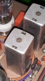
But for mixing, I like very much the ECH81 tube and had saved several of them. Also I have several K-Trans IF trafos very small and permeability tuned.
But for mixing, I like very much the ECH81 tube and had saved several of them. Also I have several K-Trans IF trafos very small and permeability tuned.
Attachments

If memory serves well, lowest possible NF with ECC88 cascode in the FM band is ~4dB. But when selectivity is prioritized (makes sense in urban environment), NF increases to ~6dB, more or less default as Marcel noticed. With planar triode in gg you might achieve ~3dB in wideband arrangement. So for 50 MHz that's useful too. For 144 MHz it isn't, a simple BF988 / 998 can easily get below 0.7 dB.
AFAIK nobody tried gc NFB with tubes. With semiconductors that topology provides optimum SWR, gain and NF simultaneously - no other topology can do that. So when using tubes, that's the first I would construct and measure (not enough tube data to simulate that). BTW my test amp performs very well (no observable IMD at output of a few 100 mV), hooked it up without measuring.
AFAIK nobody tried gc NFB with tubes. With semiconductors that topology provides optimum SWR, gain and NF simultaneously - no other topology can do that. So when using tubes, that's the first I would construct and measure (not enough tube data to simulate that). BTW my test amp performs very well (no observable IMD at output of a few 100 mV), hooked it up without measuring.
Attachments
Ok. I lack instrumentation to measure so finely the projects. I'm a humble hobbyst although I have an oscillo and the vintage EICO 368 for measuring BW.
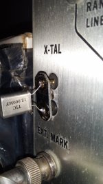
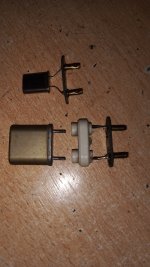
Accidentally I found that the socket for marker cristals is exactly the same as fluorescent tubes. So I reused some plugs from them for creating my own marker crystals.
Accidentally I found that the socket for marker cristals is exactly the same as fluorescent tubes. So I reused some plugs from them for creating my own marker crystals.
Attachments

Hobbyists can achieve excellent results as well. For instance, by using the ratio of Q(loaded)/Q(unloaded) to estimate how much NF will be higher than stated in the datasheet of the device. The lower the ratio, the better. Hence the effort by hams (who need lowest possible NF) to simplify the procedure / calculations:
https://www.g3ynh.info/zdocs/magnetics/appendix/optQ_hb9dfz.html
https://www.g3ynh.info/zdocs/magnetics/appendix/optQ_hb9dfz.html
Two ways to measure the noise figure are:
1. Hot-cold method with a calibrated noise source and a spectrum analyser
2. For a complete receiver: measuring the audio signal-to-noise ratio at an RF signal level a bit above threshold (for example, 10 uV EMF, 5 uV characteristically terminated voltage in a 75 ohm environment) and calculating the noise figure from that
A sound card and an audio editor suffice for measuring audio SNR. Can the sweep generator generate an FM signal with a known deviation of a few dozen kilohertz and a known level of a few microvolts?
If you just want to measure an LNA, you could connect its output to the antenna input of an FM receiver. If it has a reasonable gain, it will then dominate the noise figure of LNA + receiver.
Many thanks for all info and suggestions. My first step will be to have the receiver working, and then run optimization as you sugested.
I am still unsure about the final topology and from the tubes selected by my tube stock. Here in my place is a very difficult task to buy tubes from the foreign. Also coil formers are difficult to find and buy here.
I am still unsure about the final topology and from the tubes selected by my tube stock. Here in my place is a very difficult task to buy tubes from the foreign. Also coil formers are difficult to find and buy here.
- Home
- Source & Line
- Analogue Source
- A new FM tuner with Compactron Tubes