
Of course. I had measured a minimum of about 8pF and a maximum of 24pF which is a bit strange, but those digital LCR meters are a bit random in its measurements and I distrust them. But almost I have an idea.Osvaldo, of course you do know that it is not the capacitance value with the plates fully in alone that counts, but the quotient between plates out and plates in that has to match your desired frequency range.
I refer you to post #17 in my AM Tuner project thread. Mathematiclly will be the same.
Btw, clever idea what you did with that tuning capacitor! How exactly did you remove the superflouos plates? Did you use a slim router bit in the Dremel?
Not necessary. The sheets was soldered with tin, so easy to remove. In the pic above it is clearly visible. Only hand tools like a small electronics pliers.
I counted the original qty of them. So I leave the first, removed the 2° and 3°, leave the 4°and so on. So my new cap has triple separation. The same in the rotor and stator sets.
I don't understand if the short is in the gang. Sometimes abusing mechanically of it causes the rotor sheets to touch the fixed or stator set, making a shorted cap. In this case, viewing it with a powerful light through the cap can help identify the points of touch. Also a peculiar sounds appears when manually rotating the cap.Btw (2): Weeks ago I've removed a triple FM (plus double AM) tuning capacitor from an old so called receiver (radio + amp in one case) that suffered from a blown thick film power amp module. Sadly, one of the three parts appears to be fully shorted, and I don't recognize any reason at all for this severe issue, even not through a magnifying lens 😕.
Best regards!
I used sometimes to use a lamp in series to a power source to found the place. The lamp brights and a small spark is produced. If sheets are strongly folded, there is only one solution: sale it as aluminium.
Last edited:
The max/min ratio matters on the AM band. 0.5MC to 1.5MC is 3:1 frequency and 9:1 capacitance, a long stretch.it is not the capacitance value with the plates fully in alone that counts, but the quotient between plates out and plates in that has to match your desired frequency range.
The target capacitance MUST be smaller at higher frequency or the L would be impossibly small. This matters when you want to shift from 1MC AM to 100MC FM band. I remember 30pFd as a nominal value for FM band and reasonable (few-turn) coils. Yes, busting half or a third of the plates out of the insulator slots and shaft groove was often done for military gear re-purposed for ham-radio bands, and I see it makes sense for an AM-to-FM broadcast part conversion.

Yes, the stretch isn't than long with FM. Here in Germany FM means 87.5 to 108 MHz, the quotient is 1,23. Hence, capacitance variation needs to be (108/87.5)² = 1,52.
Best regards!
Best regards!
Btw, here's the unit that I had described above:

To my big surprise the short, which has been in the middle FM section, no longer existed when I measured again yesterday ! Perhaps I might also build a FM radio by myself?
Best regards!
To my big surprise the short, which has been in the middle FM section, no longer existed when I measured again yesterday
! Perhaps I might also build a FM radio by myself?Best regards!
Tin whiskers maybe, if the plates have a pure tin finish? Those are microscopically thin, so you can overlook them and they can break.
How do they make a reliable contact with aluminium? It grows an insulating oxide layer when it is subjected to oxygen.
I dunno, but I see the plates are stamped/crimped to the axle or the fixed supports.
Best regards!
Best regards!
Why not? Put your hands to work soonly.Btw, here's the unit that I had described above:
View attachment 1068456
To my big surprise the short, which has been in the middle FM section, no longer existed when I measured again yesterday
Best regards!
Tubes or transistors? Which is your idea?
I don't know yet. I kept the FM frontend transistors and inductors of the unit, a Wega R250SH (actually made by Sony), so I could clone the complete section. On the other hand, as I rather am a tube guy (like you 😉) and still am following your thread with big interest, why not use our thermionic friends?
Best regards!
Best regards!
Yes. I must confess my love to tubes, perticularly to compactron units. Prety wonderful performance with low size and less power waste than previous.
I am actually having some trouble for proper oscillator coil design to cover the 110 to 130MHz. It is a question of time like the Depeche Mode song say.
I would buy 6M11 tubes: a 12AT7 double triode plus a 6EW6 high gm pentode for mixer, but thanks to our economists and politics actually impossible.
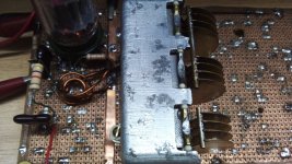
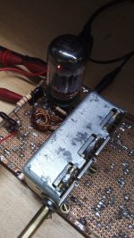
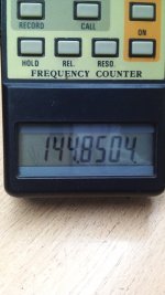
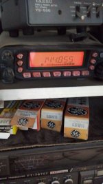
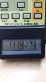
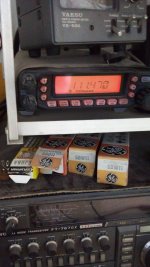
This is the really working version of the oscilator. Tube is the 6BD11 triode section 1 as manual sais. It has the higher gm of both and the lower Cpg. Observe double checking of osc. frequency on the counter and in VHF ham tranceiver. Its appearance is really ugly and no padder nor triming means. The object was to test tube VHF capability as it is not designed for the purpose.
The thing is of the tuned grid kind of oscillator with tickler coil in the anode. There is an added resistor and capacitor from the grid to ground; low pass filter with 820pF and 820K to measure grid rectification bias, a means for check oscillator health, and varies from -3.1V at the higher limit (lower C) to -2.5V at the lower freq. end. Grid leak is 18K and 22pF. Coil is 1.5T 2mm copper wire air cored; 5mm inner diameter. The grid leak resistor and capacitor are paralleled and returns to the top of osc coil and condenser. Tickler is 1.5T about 10mm dia surrounding grid tank. Plate voltage is about only 60V and is obtained from regulated 140V through a 47K 1W resistor in order to protect the tube when oscillation deads out during the experiment. Perhaps the resistor can be reduced to 18K at final artwork.
Next step will be to fix the limits to the desired 100 to 120MHz and temperature and time stability and a more mechanically stable coil. As it is actually, past about half an hour, it stays stable within 5KHz of the tranceiver IF width.
Attachments
This's the schematic of the oscillator. Remaining elements in the 6BD11 boy are still unused. Almost surely the triode will be the mixer and the pentode, the first IF. Observe again, no frequency adjustment means. The TP is the already said grid voltage monitoring point. It will be erased in the final artwork.
Attachments
Osvaldo,I would buy 6M11 tubes: a 12AT7 double triode plus a 6EW6 high gm pentode for mixer, but thanks to our economists and politics actually impossible.
although I like the short and thick appearance of compactrons, I surely prefer single tubes in RF/IF services, as I think neutralisation and suppression of parasitic oscillations is much easier this way. When the time has come, I'll probably go with an arrangement that has been common in European TV sets for the VHF frontend: A PCC88 in cascode as the input amplifier, a PCF80/82/86 as the local oscillator and frequency changer. Or I'll follow an advice given perviously: A grounded grid PC86/88 as the input amplifier.
Hopefully they won't completely shut down analog FM broadcasting before in favour of the already running DAB+ standard here in Germany...
Best regards!
Ok. The RF amplifier will be a cascode as you said and already l said in my previous posts. Many thanks for your concepts and suggestions.
Low power FM stations here are a plague and l don't think all them will stop tx simultaneously and soonly.
Purely grounded grid stages alone are of no simpaty for me. In any case I prefeer neutrode like 6EH5 or 6ER5 guided grid pets.
Low power FM stations here are a plague and l don't think all them will stop tx simultaneously and soonly.
Purely grounded grid stages alone are of no simpaty for me. In any case I prefeer neutrode like 6EH5 or 6ER5 guided grid pets.
Well, the 12AT7 never was intended as a cascode amplifier. afaik the first tube dedicated for this service was the E88CC/6922 and it's derivatives, and only some few followed. ECC2000 comes into mind. But probably your 6M11 is superior than a plain 12AT7.
Btw, here's a German amateur's FM frontend design using the ECC2000 in cascode. Hopefully you're able to have it translated into Spanish automatically.
Best regards!
Btw, here's a German amateur's FM frontend design using the ECC2000 in cascode. Hopefully you're able to have it translated into Spanish automatically.
Best regards!
My idea is the following:
A ECC88 or ECC189 or similar (both in my stock) as cascode RF amplifier.
The 6BD11: section #1 triode as oscillator. Section triode #2 as mixer. Pentode as first IF. But as you can see, the project may change unexpectedly in any moment.
I never saw an ECC2000 here nor l heared about him. The 6M11 is a 12AT7 plus a 6EW11 and may run similar to the actual 6BD11 and better, but I haven't any one at hand. If you wanna gift me one ;-) will be welcomed.
This is a crude idea of the front end of my project. Some components, RF amp and LO are more or less defined, but the mixer is still uncertain. Particularly, a small inductor placed in the plate of the mixer anode that it is said to be useful for neutralizing it. Some tuners of the tube era used it at this place or at the screen of the pentode mixer if this kind is used, particularly with 6CG8 and similar devices.
Langford-Smith in his Radiotron suggests that the first IF tuning capacitor return to ground or cathode in place of being paralleled to the IF transformer primary. This is so to ground properly undesired signals as a result from the mixing process. Who knows...
Langford-Smith in his Radiotron suggests that the first IF tuning capacitor return to ground or cathode in place of being paralleled to the IF transformer primary. This is so to ground properly undesired signals as a result from the mixing process. Who knows...
Attachments
- Home
- Source & Line
- Analogue Source
- A new FM tuner with Compactron Tubes