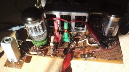
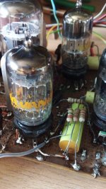
Now the oscillator has been reordered and is ready the coupling to the mixer grid (Section triode #2 of 6BD11). No yet made the RF amp and its coupling. The distance from coil to coil suffices to get about -2V at the mix grid without the plate loading wired (First IF primary).
The green bobbin is the mixer and red the oscillator. There isn't need to follow color conventions as it will be the only I build, it is for my own use and finally is what l have at hand
The green bobbin is the mixer and red the oscillator. There isn't need to follow color conventions as it will be the only I build, it is for my own use and finally is what l have at hand
Attachments
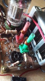

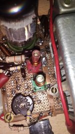
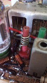
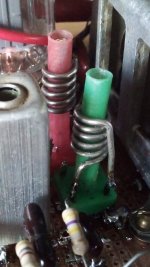
As things appears to be in the good way, I re-did the green coil using a large wire size, the same as the osc coil of about 1.2mm enameled. Then I re-place it a bit closer to the osc, in order to obtain a greater coupling. Also some space has breen freed for the RF amplifier stage, the 7 pin black socket mounted but unused.
In the pics can be viewed those changes, and the brass slugs inside the coil formers.
The red wire close to the gang is the pick up of the digital frequency meter.
In the pics can be viewed those changes, and the brass slugs inside the coil formers.
The red wire close to the gang is the pick up of the digital frequency meter.
Attachments
I must admit l am obstinate and capricious. Suspecting that when l made the cascode around triode sections of 6BH11 something was wrong because of persistent oscillations, l tryed it again with it, using the same (individual) tube, and this time it is performing as desired. Possible causes of the previuos failure may be some miswiring or faulty component. This is how actually I did it again.
Attachments
Coil data resumee:
1.- IF transformers:
Primary and secodary are the same: 24Turns 0.22mm copper wire in two layers one over other, no separation between turns; tuning by magnetic 5/32 slugs. Outer diameter of coil former 5.5mm. Tuning capacitors 22pF for the primary; 10pF for secondary plus 6JU8A and wiring capacitance (!). Shielding box square 14mm side, 40mm height, grounded.
2.- Oscillator coil:
Same former as IF but 10mm long brass slugs 5/32 screw. 3.5 turns 1.2mm copper wire enameled, no separation between turns. Wired as plate load, series DC feed. No shielding (I want to mantain magnetic coupling to mixer stage).
3.- Oscillator grid choke: nonmagnetic coil former 5mm diameter, 15mm long with axial leads. 14T 0.5mm copper wire adjusted (moving turns along form) for better oscillator performace.
The frequency coverage and activity (evaluated as the grid leak rectified voltage measured with 10Mohm VOM, a 1Mohm decoupling resistor and 820pF auxiliary low pass filter) varies both with the adjust of the slug of the main tuning inductor and the grid choke from 97 to 125MHz (12MHz IF ! ) and from -2 to -5V while rocking between both extremes of the gang.
4.- Mixer grid:
Same coil former, no shield. 4.5T 1.2mm coper wire. Primary windind may be 4T 0.5mm slideable along former for proper coupling to mixer's grid coil. Not tested yet.
5.- RF grid:
Same as above, aerial winding not defined still. May be an untuned primary or a tap in the main winding. Not tested yet. See attached pic.
Attachments

Last edited:
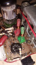
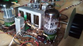
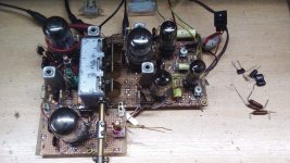
A panoramic view of how the RF front end is evoluting (or not?)
Anode load for cascoded RF amplifier is still un-done. The oscillator tank and mixer grid tuned circuit are more closer yet.
At the left is the 6BD11 oscillator and first IF, at right the 6BH11 RF amplifier (two triodes cascoded) and mixer (pentode).
There is still an unused triode unit in the former, possibly for the reactance tube for AFC.
Attachments
Once again the dual triode inside 6BH11 cascoded, turned unstable once more. Thus I discarded him to be part of the FM tuner and replaced by a high gm dual pentode 6BN11 that properly neutralized looks sufficiently stable. One section will be the mixer and the other, the RF amplifier. The origin of the failure remains unknown, but another cause may be long cathode and grid wires inside the bulb plus the other written some paragraphs above.
While the circuit is made but unadjusted, the beat with the oscillator signal could be saw with a powerful very near station although the IF is temporarily unsuplied with Ebb in order to prevent a short circuit or damage while doing the tests to RF front end.
While the circuit is made but unadjusted, the beat with the oscillator signal could be saw with a powerful very near station although the IF is temporarily unsuplied with Ebb in order to prevent a short circuit or damage while doing the tests to RF front end.
Attachments
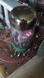
Upgrade in the grid choke of the oscillator: now it has about 1uH and has 11 turns of 0.5mm Cu wire over a 5mm diameter nonmagnetic core 16mm long with radial leads. Turns spaced about 1mm. This modifications make it more efficient (estimating efficiency roughly as the grid leak voltage) over the 98 to 122MHz range. Stability with time is good and less microphonic as the previous as the turns are more tightened to the form.
This choke is very critical for the oscillator's performance.
This choke is very critical for the oscillator's performance.
Attachments
I reordered the components around the grid choke to give it more clearance and less looses and parasitic capacitance; and added a plate decoupling choke of about 2.2ųH and a 2.4nF mica to ground to better decoupling of the oscillator. Also reduced the plate droping resistor from 18K to 15Kohm @1W to let it a little more power. It isn't so necessary such a power but this size is OK for the place and space I have available. See the 90° between chokes for the least couplig possible.
Also I moved the first IF transformer that was in an auxiliary small board (post #229) in the corner, to the main protoboard and half way between the 6BD11 & the 6BN11 boys.
Also I moved the first IF transformer that was in an auxiliary small board (post #229) in the corner, to the main protoboard and half way between the 6BD11 & the 6BN11 boys.
Attachments
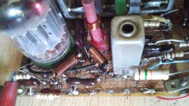
More news: l removed the 6AL5 double diode and his socket and placed there a 6BV8A which plus the dual diode includes a medium mu triode, wired as cathode follower, to get a low impedance output to the existing audio system. Thus, l recalibrated the first and forth IF trafos (the former because of the added mixer 6BN11 and the latter for the different diode internal capacitance). It is highly possible next week it plays his first song or words. Prior to it l need to investigate which is the proper alignment for the entire IF stage and the proper adjustement of the k's of them.
Below is the new guy and at its right the CF biasing elements. On his left, the Foster Seeley detector passive components. At the back, the 6JU8A quad diode both of them are the limiters. All Sylvania tubes NOS.
Below is the new guy and at its right the CF biasing elements. On his left, the Foster Seeley detector passive components. At the back, the 6JU8A quad diode both of them are the limiters. All Sylvania tubes NOS.
Attachments
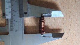
Still anorher oscillator coil. This time with copper wire (silver?) plated, one more turn and more spaced turns for better RF performance. It is also larger wire size: 1.5mm diameter. I have some more cm's of it so the RF and antenna coil will be re-done the same wire.
Attachments
I haven't commented on anything for quite some time, but it's nice to see your updates!
Regarding skin effect, I've always been scratching my head why you didn't use silver plated copper wire right from the beginning, but didn't dare to argue due your obviously more sophisticated competence in AF themes 😉.
Anyway, I still don't understand why you chose 12 MHz as the IF, instead of the quite more usual 10.7 MHz. The lower the IF, the higher the discriminator's AF output with the same FM sweep and the higher S/N ratio, I'd say.
Best regards!
Anyway, I still don't understand why you chose 12 MHz as the IF, instead of the quite more usual 10.7 MHz. The lower the IF, the higher the discriminator's AF output with the same FM sweep and the higher S/N ratio, I'd say.
Best regards!
There is an equation in FM theory that says the higher the IF the lower the THD, and very occasionally tuners have been built with non-standard IFs, whether to exploit this equation or for some other reason it is now impossible to say. Oswaldo gave his reasons, but this wasn't among them. I deal with such tuners, 12.5MHz IF, and I can assure you they are a royal PITA, as you have to do the whole alignment without the aid of a definitive marker: only guesswork.
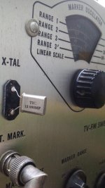
Ok. In my case, none of the two arguments are certain. I choose it for better image rejection as l have several christians & clandestine FM stations near me. I counted almost 7 (seven) towers with its radiators in a 1km radii circle. I saw some strange IF values as 4.3 MHz, so why not to try my own one. Another marginal advantage is that I have several 12MHz crystals for the EICO 368 generator but no one of 10.7MHz.
Respect to the silvered wire, l was investigating about home plating. I have saved some small bits of silver. As copper electroplating is easy to do homebrewed, silver plating seems some more difficult as silver nitrate is expensive. Looking for the coductivity between copper and silver, there is a ratio of 0.95 so really l don't know if this small difference justifies the effort.
There is no obligation for nobody to post here if he doesn't want. Post here all that sincerely want to be my companions in this project.
Attachments
My reasoning behind silver plating was that at least here it is, or has been commonly used in TV VHF or UHF frontends, despite of the small difference in conductivity between Ag and Cu.
Btw, 4.3 MHz was the standard frequency in analog TV IF strips here.
Best regards!
Btw, 4.3 MHz was the standard frequency in analog TV IF strips here.
Best regards!
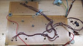
Here are two pics of a general perspective of the Frakestein. One is the top, and the other, the bottom where run heater wiring in order to not obstruct the main side. There are several undocumented 10nF plate caps across each socket in order to bypass them for RF currents.
Attachments
Ok. l know that silver plated wires perform better in VHF but sincerely unknow how much better. And if this improvement is measurable, more over considering I am doing it at eye, little instrumental here.My reasoning behind silver plating was that at least here it is, or has been commonly used in TV VHF or UHF frontends, despite of the small difference in conductivity between Ag and Cu.
Btw, 4.3 MHz was the standard frequency in analog TV IF strips here.
Best regards!
5.5 MHz was the standard monaural television audio carrier frequency offset in PAL television, 4.43361875 MHz was used for the colour subcarrier. (There was a reason why that specific frequency led to optimal compatibility with the older black-and-white television standards, but it was so complicated I don't remember the details.)
Good to see progress. One reason to use silver plated coils is that due to the air (and pollution), oxides form. Whereas silver oxide still is a conductor, copper oxides are semiconductors (nonlinear effects). Some even use "RF proper" varnish coating on the silver plating, to prevent oxidation.
With such an amount of nearby transmitters, it's good practice to choose an IF high enough to guarantee absence of image reception. In that respect, higher is better. The problem arises with limiting, when harmonics leak into the input circuits. In my tube receivers with 10.7 IF, major culprit was the 9th, resulting in lower sensitivity at around 96.3 MHz. It was one of the reasons to change topology to 2nd conversion with "low enough" 2nd IF.
With such an amount of nearby transmitters, it's good practice to choose an IF high enough to guarantee absence of image reception. In that respect, higher is better. The problem arises with limiting, when harmonics leak into the input circuits. In my tube receivers with 10.7 IF, major culprit was the 9th, resulting in lower sensitivity at around 96.3 MHz. It was one of the reasons to change topology to 2nd conversion with "low enough" 2nd IF.
- Home
- Source & Line
- Analogue Source
- A new FM tuner with Compactron Tubes